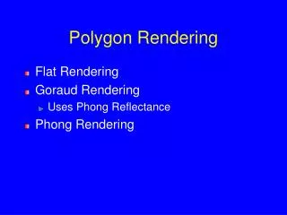
Polygon Rendering
Polygon Rendering. Swapping the Loops. Review: Ray Tracing Pipeline. Ray tracer produces visible samples of scene Samples are convolved with a filter to form pixel image Ray tracing pipeline:. -Traverse scene graph -Accumulate CTM -Spatially organize objects.

Polygon Rendering
E N D
Presentation Transcript
Polygon Rendering Swapping the Loops
Review: Ray Tracing Pipeline • Ray tracer produces visible samples of scene • Samples are convolved with a filter to form pixel image • Ray tracing pipeline: -Traverse scene graph -Accumulate CTM -Spatially organize objects Acceleration Data Structure (ADS) suitable for raytracing Preprocessing Scene Graph Evaluate lighting equation at sample -traverse ADS -for nearest cell to farthest cell -intersect objects in cell with ray -return nearest intersection in cell -otherwise continue to next cell Generate ray for each sample Ray Tracing Generate reflection rays Post processing Convolve with filter All samples Final image pixels
Rendering Polygons • Often need to render triangle meshes • Ray tracing works well for implicitly defined surfaces • Many existing models and modeling apps are based on polygon meshes – can we render them by ray tracing the polygons? • Easy to do: ray-polygon intersection is a simple calculation (use barycentriccoords) • Very inefficient: It’s common for an object, to have thousands of triangles, for a scene therefore hundreds of thousands or even millions of triangles – each needs to be considered in intersection tests • Traditional hardware pipeline is more efficient for many triangles: • Process the scene polygon by polygon, using “z-buffer” to determine visibility • Local illumination model • Use crude interpolation shading approximation to compute the color of most pixels
Traditional Fixed Function Pipeline (disappearing) • Polygons (usually triangles) approximate the desired geometry • One polygon at a time: • Each vertex is transformed into screen space, illumination model evaluated at each vertex. NO GLOBAL ILLUMINATION (except through ambient term hack) • One pixel of the polygon at a time (pipeline highly simplified): • Depth is compared against z-buffer; if the pixel is visible, color value is computed using either linear interpolation between vertex color values (Gouraud shading) or (better) a crude local lighting model for each pixel (e.g., Phong shading using interpolated normals) Geometry Processing World Coordinates Rendering/Pixel Processing Screen Coordinates Image-precision VSD: compare pixel depth (z-buffer) Selective traversal of Acc Data Str (or traverse scene graph to get CTM) Transform vertices to canonical view volume Lighting: calculate light intensity at vertices (lighting model of choice) Back-face culling (next slide) View volume clipping Shading: interpolate vertex color values (Gouraud) or normals (Phong)
Visible Surface Determination • Back face culling: • Often don’t need to render triangles “facing away” from camera • Know that triangle’s vertices are listed in a particular order (usually counter-clockwise, by convention) • If screen space vertex positions aren’t in counter clockwise order, camera is facing back of triangle and it can be skipped • View volume clipping: • If triangle lies entirely outside of view volume, no need to render it because it can’t be seen • Some special cases requiring polygon clipping: large triangles, triangles near edges of the view volume (i.e., triangles that intersect or overlap faces of the view volume.) Analogous to 2D case where we cannot trivially accept or reject using simple outcode tests comparing vertex coordinates against clip bounds • Occlusion culling, triangles (meshes, bounding boxes,…) that are behind other opaque triangles don’t need to be rendered
Programmable Shader Based Pipeline • To allows programmer to fine tune and optimize rendering, various stages of pipeline are customizable • You’ve played with shaders in lab • Shadersare fast! (They use multiple ultra-fast ALU’s). Using shaders even all of more advanced techniques mentioned in this lecture can be done in real time. • Physical phenomena such as shadows (slides 18, 19) and light refraction can be emulated using shaders. The image on the right is rendered with a custom shader. Note that only the right image has realistic shadows. A normal map is also used to add detail to the model.
Simple Shading Models Compared Constant shading: no interpolation, pick a single representative intensity and propagate it over entire object. Loses almost all depth cues. Pixar “Shutterbug” images from: www.siggraph.org/education/materials/HyperGraph /scanline/shade_models/shading.htm
Simple Shading Models Compared Flat or Faceted Shading: constant intensity over each face Constant Shading
Simple Shading Models Compared GouraudShading: Linear Interpolation of intensity across triangles to eliminate edge discontinuity Flat Shading
Simple Shading Models Compared PhongShading: Interpolation of vertex surface normals Note: specular highlights but no shadows. Still a pure local illumination model Gouraud Shading
Simple Shading Models Compared Global Illumination: Objects enhanced using shadow, texture, bump, and reflection mapping (see S20) Phong Shading
Shading Models (1/6: Faceted) • Faceted Shading: • Single illumination value per polygon • With many polygons approximating a curved surface, this creates an undesirable faceted look. • Facets exaggerated by “Mach banding” effect
Shading Models (2/6: Gouraud) • Illumination intensity interpolation • Illumination values are computed at vertices, linearly interpolated across the pixels of the polygon • Eliminates intensity discontinuities at polygon edges; still have gradient discontinuities. • Mach banding is largely ameliorated, not eliminated • Must differentiate desired creases from tesselation artifacts (edges of cube vs. edges on tesselatedsphere) • Step 1: Compute vertex normals byaveraging surrounding polygon normals
Shading Models Explained (3/6: Gouraud cont.) • Step 2: Evaluate illumination at each vertex using lighting model , • Step 3: Interpolate illumination along polygon edges • Step 4: Interpolate illumination along scan lines scan line
Shading Models (4/6: Gouraud cont.) • Takes advantage of scan line algorithm for efficiency • is constant along polygon edge, is constant along scan line • Gouraud vs. Faceted shading:
Shading Models (5/6: Gouraud cont.) • Gouraud shading can miss specular highlights because it interpolates vertex colors instead of calculating intensity directly at each point, or even interpolating vertex normals(Phong shading) • and would cause no appreciable specular component, whereas would, with view ray aligned with reflection ray. Interpolating between Ia and Ibmisses the highlight that evaluating I at c using would catch • Phong shading: • Interpolated normal comes close to the actual normal of the true curved surface at a given point • Reduces temporal “jumping” affect of highlight, e.g., when rotating sphere during animation (example on next slide)
Shading Models (6/6: Phong Shading) • Phong Model: normal vector interpolation • Interpolate N rather than I • Always captures specular highlights, but computationally expensive • At each pixel, N is recomputed and normalized (requires sq. root operation) • Then I is computed at each pixel (lighting model is more expensive than interpolation algorithms) • This is now implemented in hardware, very fast • Looks much better than Gouraud, but still no global effects Gouraud Phong http://www.cgchannel.com/2010/11/cg-science-for-artists-part-2-the-real-time-rendering-pipeline/ Gouraud Phong http://en.wikipedia.org/wiki/Gourad_shading
Shadows (1/5) – Simplest Hack • Render each object twice • First pass: render normally • Second pass: use transformations to compress object onto ground plane, render completely black • Pros: Easy, can be convincing. Eye more sensitive to presence of shadow than shadow’s exact shape • Cons: Becomes complex computational geometry problem in anything but simplest case • Easy: projecting onto flat, infinite ground plane • How to implement for projection on stairs? Rolling hills? http://web.cs.wpi.edu/~matt/courses/cs563/talks/shadow/shadow.html
Shadows (2/5) – More Advanced • For each light For each point in scene If is in shadow cast by Only use indirect lighting (e.g., ambient term for Phong lighting) Else Evaluate full lighting model (e.g., ambient, diffuse, specular for Phong) • Next up: different methods for computingwhether is in shadow cast by Stencil shadow volumes implemented by former cs123 ta and recent Ph.D. Kevin Egan and former PhD student and book co-author Prof. Morgan McGuire, on nVidia chip
Shadows (3/5) – Shadow Volumes • For each light + object pair, compute mesh enclosing area where object occludes the light • Find silhouette (filled in outline of object from light’s perspective): every edge shared by two triangles, such that one triangle faces light source and other faces away • On torus, where angle between and becomes 90 • Project silhouette along light rays • Generate triangles bridging silhouette and projection • A point is in shadow from light if • shadow volume computed for such that is inside • Can determine quickly using stencil buffer • Combined technique called ‘Stencil Shadow Volumes’ • More here on Stencil Buffers, Stencil Shadow Volumes Original Silhouette Projected Silhouette Example shadow volume (yellow mesh) http://www.ozone3d.net/tutorials/images/stencil_shadow_volumes/shadow_volume.jpg
Light Shadows (4/5) – Shadow Maps • Render scene from point of view of light, saving depths instead of colors per pixel • Disable rendering to color buffer and render normallyfrom light’s point of view • Depth: world-space distance from light source to object under that pixel • Result: 2D image called a “shadow map” • To determine if point on object is in shadow • Compute distance from to light source • Look up min distance in shadow map • Find pixel (depth value ) where line from to passes through shadowmap • in shadow if Shadow Map Visualization of Shadow Map http://graphics.cs.williams.edu/papers/CSSM/nalgene-Williams-shadowmap.png
Shadows (5/5) – Shadow Map Tradeoffs • Pro: Can extend to support soft shadows • Stencil shadow volumes only useful for hard-edged shadows • Con: Naïve implementation has impressively bad aliasing problems • Many screen pixels covered by projection of one shadow map pixel • Doesn’t make sense to filter shadow map (interpolating depth samples) • Many workarounds for aliasing issues • Percentage-Closer Filtering: box blur by samplingshadow map in multiple places • Cascaded Shadow Maps: multiple shadow maps,denser resolution closer to viewer • Variance Shadow Maps: use statistical modelinginstead of simple depth comparison http://www-sop.inria.fr/ reves/Marc.Stamminger/psm/
Comment About Different Kinds of Maps • Originally designed for offline rendering to improve quality • Now used in shader programming to provide real time quality improvements • Maps can be used in combination • Many are additions to or variants of texture mapping • Skybox/Environment map with shadow maps • Shadow map with normal map • Parallax map with normal map • Simple Idea: Mipmapping • Use lower resolution textures for objects further away • Example of level of detail management • Maintain multiple texture maps at different resolutions • MIP: multum in parvo, “much in little”
Environment Mapping (for Shiny Objects) (1/2) • Approximate reflections by only reflecting skybox • Skybox a.k.a. environment map a.k.a. reflection map • Environment map encloses 3D space • e.g. six faces of a cube surrounding scene • To sample at point • Compute vector from to eye(negative view ray) • Reflect about normal to obtain • From center of environment map, move indirection of until finding a sample • Treat as being in the center of map; equivalently,treat environment map as being infinitely large Skybox Object
Environment Mapping (2/2) • Non-trivial to reflect other objects in the scene • Achieved by rendering the entire scene, and storing results into faces of the environment map • Can do this offline for static geometry, but must generate at runtime for moving objects • Rendering environment map at runtime is expensive • Not limited to six-sided textured skyboxes • e.g. can use a single 2D map ‘unwrapped’from surface of a sphere. Choose sample points by calculating longitude and latitude • See “Texture Mapping of Sphere” in TextureMapping lecture http://www.juztn.com/CompTut/compTut7.html
Overview: Surface Detail • These spheres have same geometry: • Observation • What if we replaced the 3D sphere on the right with a 2D circle? • The circle would have fewer triangles (thus renders faster) • If we kept the sphere’s normals, the circle would still look like a sphere! • Works because human visual system infers shape from patterns of light and dark regions (“shape from shading”). Lightness at any point is determined by normal vector, not by actual geometry of model. Image credit: Dave Kilian, ‘13
Idea: Surface Detail • Start with a hi-poly model • Decimate the mesh (remove triangles) • Encode hi-poly normal information into texture • Map texture onto lo-poly mesh • Use fragment shader to look up normal for each pixel • Use Phong shading to calculate pixel color • Replace with value computed from texture • Next: how to encode normals in texture? Original hi-poly model Lo-poly model with hi-polymodel’s normals preserved
Object-space normal map Tangent-space normal map Normal Mapping • Easiest to render, hardest to produce • Usually need specialized modeling toolslike Pixologic’sZBrush • Idea: Fill a texture with normals • Fragment shader samples 2D color texture • Interprets R as , G as , B as • Uses to do light calculations • Variants • Object-space: encodes normal itself • Tangent-space: encodes normal relativeto object’s original normal Images: www3.telus.net, www.bitmanagement.com
Normal Mapping Example • Normal mapping can completely alter the perceived geometry of a model • Normal map gives model finer detail • Render showing simple underlying geometry Image courtesy of www.anticz.com
Normal Mapping Video http://www.youtube.com/watch?v=RSmjxcAhkfE
Aside: Creating Normal Maps • Automated • Original mesh simplified to mesh • Normal map texture coords assigned to • For each pixel in normal map • Find corresponding point on : • Find closest point on original mesh: • Average nearby normals in and save value in normal map • Manual • Artist starts with • Uses specialized tools to draw directly onto normal map (‘sculpting’)
Bump Mapping: Example = + Original object (plain sphere) Bump map (height map to perturb normals - see next slide ) Sphere with bump-mapped normals http://cse.csusb.edu/tong/courses/cs520/notes/texture.php
Height map Bump Mapping • Idea: instead of encoding normals themselves, encode relative heights • Black: minimum height delta, White: maximum height delta • Much easier to create than normal maps • Use height deltas to perturb the normal • To sample bump map • Collect several height samples from texture • Approximate gradient using height samples • Transform from tangent space to object space • Tangent space: XYZ system, where Z is alignedwith the original normal Tangent Space (using left-handed coordinate system) http://jahovaos.com/groups/kb/wiki/19ed6/Relief_Mapping__Normal_Mapping.html
Other Techniques: Displacement Mapping • Move vertices along normals by looking up height deltas in a height map • Doesn’t provide extra detail like normal/bump mapping • Useful for animating surfaces The displacement map used to render the scene. The intensity value indicates the height at a given point. http://www.creativemac.com/2004/02_feb/tutorials/koc4ddisplace040224.htm
Other Techniques: Parallax Mapping • Extension to normal mapping • Distorts texture coordinates right before sampling, as a function of normal and eye vector • Example image on right: looking down at bricks from above • Texture coordinates stretched near top of brick, where you should be able to ‘see’ the top of the brick • Similarly, texture coordinates compressed near bottom of brick, where you shouldn’t be able to ‘see’ the underside of the brick Texture and Parallax Mapped Texture Mapped
Other Techniques: Parallax Mapping • Actually rendering point which has texture coords • Pretending to render which has texture coords • Compute by tracing the Eye ray a short distance, then drop the vertical component ( component in tangent space). Add result to . • How far should we trace Eye ray? Approximate! • height-map height at • arbitrarily chosen scale factor • : arbitrarily chosen bias • Then http://www.opengl.org/sdk/docs/tutorials/TyphoonLabs/Chapter_4.pdf
Other Techniques: Steep Parallax Mapping • Extension on Parallax Mapping • Uses ray-marching to intersect ray with parts of heightmap parallax mapping might have missed • Adds support for self-shadowing • Invented by Brown PhD ‘06 Morgan McGuire and Max McGuire http://www.opengl.org/sdk/docs/tutorials/TyphoonLabs/Chapter_4.pdf (modified)
Comparison Creases between bricks look flat Creases look progressively deeper Objects have self-shadowing