Download
1 / 33
390 likes | 700 Views
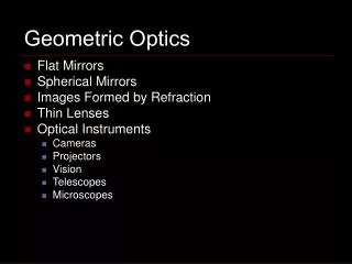
Physics 1025F Geometric Optics. OPTICS. Dr. Steve Peterson Steve.peterson@uct.ac.za. Chapter 23 : Geometric Optics. In this section, we will use the ray model of light to understand the formation of images by mirrors and lenses through the processes of reflection and refraction .

E N D
Physics 1025FGeometric Optics OPTICS Dr. Steve Peterson Steve.peterson@uct.ac.za
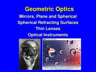
Chapter 23: Geometric Optics In this section, we will use the ray model of light to understand the formation of images by mirrors and lenses through the processes of reflection and refraction.
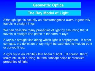
The Ray Model of Light Light rays appear to travel in straight lines. This assumption is the basis of geometric optics. The straight line paths that the light follows are called light "rays". A light ray is a line in the direction of the flow of radiant energy.
Light: An Electromagnetic Wave In actual fact, light is an electromagnetic wave, as are radio, UV, infrared, gamma and micro-waves. An electromagnetic wave is composed of electricand magnetic waves which are perpendicular to each other, and to the direction of propagation.
Electromagnetic Spectrum Electromagnetic waves can have any wavelength; there are different names given to different parts of the spectrum. The human eye only responds to EM waves in the wavelength range 400 - 700 nm, and we refer to these electromagnetic waves as "light".
Light: An Electromagnetic Wave This is the speed of all electromagnetic waves (including light) in free space (vacuum). In gases, transparent liquids and solids light travels more slowly. Maxwell calculated the speed of propagation of electromagnetic waves, he found:
Index of Refraction The index of refraction of a medium is the ratio of the speed of light in vacuum(c) to the speed of light in the medium (v): The index of refraction is never less than 1, and values for various materials are given in Table 23-1.
Reflection and Refraction When light encounters a boundary between two media the radiant energy can be: (i) reflected (ii) transmitted (iii) absorbed
Laws of Reflection and Refraction • The incident, reflected and transmitted rays all reside in the same plane (the “plane of incidence”) which is normal to the plane of the interface. • The angle of incidence = angle of reflection. (ϴ1 = ϴ1’) • The angle of refraction (ϴ2) and the angle of incidence (ϴ1) are related by Snell's law. • Light rays are reversible.
Law of Reflection Law of reflection: the angle of reflection (that the ray makes with the normal to a surface) equals the angle of incidence.
Diffuse vs. Specular Reflection When light reflects from a rough surface, the law of reflection still holds, but the angle of incidence varies. This is called diffuse reflection. With diffuse reflection, your eye sees reflected light at all angles. With specular reflection (from a mirror), your eye must be in the correct position.
Image Formation by a Plane Mirror What you see when you look into a plane (flat) mirror is an image, which appears to be behind the mirror. This is called a virtual image, as the light does not go through it. Virtual images are formed: behind the mirror. Real images are formed: in front of the mirror. The distance of the image from the mirror is equal to the distance of the object from the mirror.
Refraction When light passes from one transparent medium to another, the velocity of the transmitted light changesdepending on the material properties (index of refraction). If the light enters at an angle, the light ray will be bent or refracted as it crosses the boundary between the mediums.
Refraction: Snell’s Law From less dense to more dense, light bends towards the normal. From more dense to less dense, light bends away from the normal.
Refraction at a Plane Surface The angle of refraction depends on the indices of refraction, and is given by Snell’s law: • If , then and therefore . i.e. the ray is refracted towards the normal when passing from a less dense to more dense medium. • If , then and therefore . i.e. the ray is refracted away from the normal when passing from a more dense to a less dense medium.
Total Internal Reflection Consider the situation where a light ray is travelling from a more dense medium to a less dense medium (i.e). As we increase the angle of incidence the angle of refraction must also increase as we must satisfy .
Total Internal Reflection At some stage. The angle of incidence at which this happens is called the "critical angle", . If we increasebeyond then we no longer satisfy Snell's law and so no refraction occurs, i.e. no light is transmitted, all the light is totally internally reflected.
Application: Fiber Optics Total internal reflection is also the principle behind fiber optics. Light will be transmitted along the fiber even if it is not straight. An image can be formed using multiple small fibers.
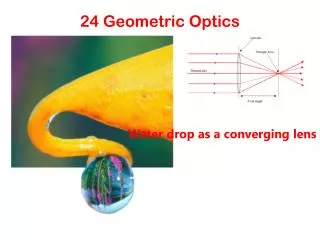
Thin Lenses Thin lenses have faces which are portions of a sphere. The two faces can be convex, concave or planar. The thickness of a thin lenses is small compared to their radius of curvature. They may be either converging / convex(a) or diverging / concave(b).
Convex (Converging) Lens Rays parallel to the principle axis incident on a convex lens are focused at a single point, the “focal point“ (F). The distance from the focal point to the centre of the lens is referred to as the “focal length”. If parallel rays fall on the lens at an angle to the principle axis then they are focused at point Fa in the “focal plane” of the lens.
Concave (Diverging) Lens For a concave lens, parallel rays that pass through the lens appear to diverge from a single point F, the focal point of the diverging lens. The focal point is that point where the diverging rays would converge if projected back.
Power of a Lens Optometrists and ophthalmologists use the reciprocal of the focal length (in metres) to indicate the strength of a lens. The unit of power is the diopter D (which is actually m-1.)
Convex Lens: Ray Tracing We use ray diagrams to determine where an image will be. For thin lenses, we use threekey rays, all of which begin on the object: • This ray comes in parallel to the axis and exits through the focal point. • This ray comes in through the focal point and exits parallel to the axis. • This ray goes through the centerof the lens and is undeflected.
Convex Lens: Thin Lens Equation Geometrically, we can derive an equation that relates the object distance (do), image distance (di), and focal length (f) of the mirror:
Magnification We can also find the magnification (ratio of image height, hi to object height, ho). By convention we introduce a – sign. If m is positive, the image is upright. If m is negative, the image is inverted.
Convex Lens: Ray Tracing We use ray diagrams to determine where an image will be. For thin lenses, we use threekey rays, all of which begin on the object: • This ray comes in parallel to the axis and exits through the focal point. • This ray comes in through the focal point and exits parallel to the axis. • This ray goes through the centerof the lens and is undeflected.
Concave Lens: Ray Tracing We use the same basic threerays, all starting from the object, except: • This ray starts parallelto the axis, but and exits in line with the focal point in front of the lens. • This ray travels toward the far focal point and exits parallel to the axis. • This ray goes through the centerof the lens and is undeflected.
Sign Conventions fis positive for a convex/converginglens is negative for a concave/diverginglens dois positive for a real object is negative for a virtual object diis positive for a real image is negative for a virtual image
Sign Conventions To decide whether an object or image is realor virtual: For realobjects the rays arriving at the lens are diverging, For virtualobjects the rays arriving at the lens are converging. For realimages the rays leaving the lens are converging, For virtualimages the rays leaving the lens are diverging.
Sign Conventions: Alternative The sign convention rules: • The focal length is positive for converging lenses and negative for diverging. • The object distance is positive when the object is on the same side as the light entering the lens (not an issue except in compound systems); otherwise it is negative. • The image distance is positive if the image is on the opposite side from the light entering the lens; otherwise it is negative. • The height of the image is positive if the image is upright and negative otherwise.
The Lensmaker’s Equation The Lensmaker's equation relates the focal length of a lens to the radii of curvature R1and R2of the two surfaces of the lens. where n1is the refractive index of the medium surrounding the lens, n2the refractive index of the lens, and R1and R2are the radii of curvature of the front and back surfaces, respectively. In order to apply this equation correctly to both convex and concave surfaces we must adopt the following sign convention for radii of curvature. R is positive for convex surfaces is negative for concave surfaces when viewed from outsidethe lens
The Lensmaker’s Equation • This useful equation relates the radii of curvature of the two lens surfaces, and the index of refraction, to the focal length.