Shift/Rotate, Cycle Counting, Stacks
Shift/Rotate, Cycle Counting, Stacks. Notes: Have you picked up your pocket reference yet? We’ll use them in lecture today… Today: First Hour : Shift/Rotate, Cycle Counting Section 2.9-2.10 of Huang’s Textbook In-class Activity #1 Second Hour : Stacks

Shift/Rotate, Cycle Counting, Stacks
E N D
Presentation Transcript
Shift/Rotate, Cycle Counting, Stacks • Notes: • Have you picked up your pocket reference yet? • We’ll use them in lecture today… • Today: • First Hour: Shift/Rotate, Cycle Counting • Section 2.9-2.10 of Huang’s Textbook • In-class Activity #1 • Second Hour: Stacks • Section 3.3, 3.6, 3.7 of Huang’s Textbook • In-class Activity #2
Arithmetic Shift Left Apply to a memory location and accumulators A, B and D. There are three 8-bit arithmetic shift left instructions: ASL opr memory location opr is shifted left one place ASLA accumulator A is shifted left one place ASLB accumulator B is shifted left one place 0 b7 ----------------- b0 C Has the effect of multiplying by 2
Shift Instructions 16-bit arithmetic shift left instruction: ASLD b7 ----------------- b0 b7 ----------------- b0 0 C accumulator A accumulator B Arithmetic shift right. E.g.: ASR opr memory location opr is shifted right one place ASRA accumulator A is shifted right one place C b7 ----------------- b0 Note: Divides by 2 each time A negative number remains negative after shifting
Shift & Rotate Instructions Logical shift left instructions. E.g.: LSL opr memory location opr is shifted left one place LSLA accumulator A is shifted left one place 0 C b7 ----------------- b0 Logical shift right instructions: LSR opr memory location opr is shifted right one place LSRA accumulator A is shifted right one place b7 ----------------- b0 C 0 Useful for unsigned multiply and divide by 2
Shift & Rotate Instructions Rotate left instructions that operate on 9-bit operands. ROL opr memory location opr is rotated left one place ROLA accumulator A is rotated left one place ROLB accumulator B is rotated left one place b7 ----------------- b0 C Rotate right instructions: Eg: ROR opr memory location opr is rotated right one place RORA accumulator A is rotated right one place b7 ----------------- b0 C Useful for controlling stepper motors, computing checksums, etc.
The 6811 manual lists the number of clock cycles that each instruction takes How long is a clock cycle? Let’s look it up. Execution time = # cycles x time per cycle Table: Execution times of a sample of instructions Execution time (E clock cycles) Instruction BNE <rel> 3 DECB 2 DEX 3 LDAB <imme> 2 LDX <imme> 3 NOP 2 How long does a program take to run? 500ns
Example LDX #2 ; 3 cycles again NOP ; 2 cycles NOP ; 2 cycles DEX ; 3 cycles BNE again ; 3 cycles Time = (3 + 102) cycles
Program Execution Time ExampleWrite a program loop to create a delay of 100 ms. Solution: A delay of 100 ms can be created by repeating the previous loop 20000 times. The following instruction sequence creates a delay of 100 ms. LDX #20000 AGAIN NOP NOP DEX BNE AGAIN Longer delays can be created by using nested program loops.
Time Delays • There are two ways to generate time delays using the 68HC11 • Timer-based interrupts • Cycle counting Let's explore the cycle counting technique Interrupt methods come later Let's see about generating a 1 ms delay subroutine
Do Activity #1 Now ExampleWrite a program loop to create a delay of 100 ms. Solution: A delay of 100 ms can be created by repeating the previous loop 20000 times. The following instruction sequence creates a delay of 100 ms. LDX #20000 AGAIN NOP NOP DEX BNE AGAIN Much longer delays can be created by using nested program loops. Things to do: Choose number of times to do the loop Add NOP instructions as “padding” if needed
8-bit Accumulators A & B 7 B 0 7 A 0 16-bit Accumulator D 15 D 0 16-bit Index Register IX 15 IX 0 16-bit Index Register IY 15 IY 0 15 PC 0 Program Counter 15 SP 0 Stack Pointer Carry/borrow (MSB) oVerflow (2s C) Zero Negative Half carry (bit 34),(BCD) SXHINZVC Condition Code Register Complete Programmer's Model STOP disable X-interrupt mask I-interrupt mask
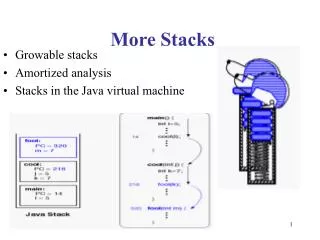
Very important data structure Also a source of headaches Very demanding, requires discipline If a stack is messed up by even one byte, a computer is likely to “crash” A “last-in first-out” data structure A queue is a first-in first-out structure May be implemented differently on different computers Let’s study the 6811 stack…. Stacks
Stack Area cell Top of Stack 15 SP 0 Stacks on 68HC11 Low address Stacks Grow down, toward low memory Data PuSHed on the stack (PSH) PULled off the stack (PUL) Always PUL as many times as PSH High address empty Stack Pointer The Stack Pointer always points to the next empty cell on the stack
SP SP PuSHing Data on Stacks Stack Area SP decrements and points to empty cell empty empty data SP points to empty cell Data is PuSHed on the stack
XX SP = $00FD SP = $00FE $20 XX $33 $33 after PSHA after PSHB PUSH A = $33, B = $20, SP = $00FF. Question 1: What will the top byte of the stack contain before and after a PSHA? Question 2: What will the top two bytes of the stack contain if PSHB is executed? XX SP = $00FF original stack
SP SP PULling Data off Stacks Stack Area SP points to empty cell SP increments empty data empty Data is PULled off stack SP points to empty cell
Used together Stack Instructions Reserve a Stack Area, e.g., 256 cells: ORG $0000 STACK RMB 256 INITSP EQU * - 1 Top of Stack Initialize the Stack Pointer: INIT LDS #INITSP Push Registers on Stack: PSHA Push ACCA PSHB Push ACCB PSHX Push IX (2 bytes) PSHY Push IY (2 bytes) Similarly, PULA, PULB, PULX, and PULY
More Stack Instructions Transfer Registers: TSX SP+1 X TSY SP+1 Y TXS IX-1 SP TYS IY-1 SP Notice the increment SP and decrement IX, IY Increment / Decrement Stack Pointer: INS SP+1 SP DES SP-1 SP Load / Store Stack Pointer: LDS M:M+1 SP IMM, DIR, EXT, indX, indY STS SP M:M+1 DIR, EXT, indX, indY Lots of addressing modes !!
Subroutines Program Structure Subroutine Processing Main program Main program <call> sub_x . . Subroutine 1 Subroutine 2 Subroutine 3 . sub_x: . Subroutine 1.1 Subroutine 2.1 Subroutine 3.1 . . Subroutine <return> Subroutine 2.1.1 Subroutine 2.1.2
SP SP Subroutine Instructions Stack Area JSR, BSR push Return Address on Stack Subroutine call: JSR BSR empty empty RTNH Subroutine return: RTS empty RTHL RTS pulls Return Address off Stack RTN is the address of the instruction following the subroutine call
Checklist: Remember that stack grows to lower memory addresses Initialize stack pointer Create enough space for all items that need to be pushed to the stack Push return address and other information on stack Jump or Branch to the subroutine. Special steps for different types of parameter passing methods Execute subroutine RTS pulls return address off stack Subroutine Checklist
Do Activity #2 Now • Due: End of Class Today. • RETAIN THE LAST PAGE(S) (#3 onwards)!! • For Next Class: • Bring Huang Textbook, & HC11 PRG • Required Reading: • Sec 3.9-3.11 of Huang • This reading is necessary for getting points in the Studio Activity!