Binary Counter with Decimal and Gray Encoding
ELEC 5270 – Low Power Design of Electronic Circuits Spring 2009. Binary Counter with Decimal and Gray Encoding. Grant Lewis. Decimal Encoding. 3-bit Counter has 14 transitions in 8 cycles 14/8 = 1.75 transitions per cycle N-bit Counter has 2(2 N -1) transitions

Binary Counter with Decimal and Gray Encoding
E N D
Presentation Transcript
ELEC 5270 – Low Power Design of Electronic Circuits Spring 2009 Binary Counter with Decimal and Gray Encoding Grant Lewis
Decimal Encoding • 3-bit Counter has 14 transitions in 8 cycles • 14/8 = 1.75 transitions per cycle • N-bit Counter has 2(2N-1) transitions • Transitions per cycle → 2 as N→ ∞ 4-bit 1.875 transitions/clock 5-bit 1.9375 6-bit 1.96875 7-bit 1.984375 8-bit 1.9921875 9-bit 1.99609375
Decimal Encoding • A = • B = • C = • 8 logic gates Synthesize in Leonardo Spectrum
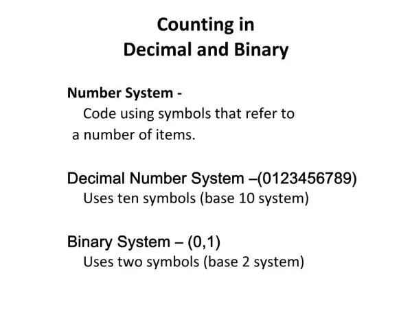
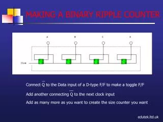
Gray Encoding • 3-bit counter has 8 transitions in 8 cycles • 8/8 = 1 transition per cycle • N-bit counter has 2N transitions • Transitions per cycle is 1 for any size counter • For large counters, ratio of transitions for Decimal to Gray → 2
Gray Encoding • Gray Encoding can be accomplished by • Binary to Gray conversion • Directly Synthesizing Gray Counter • Binary to Gray conversion is accomplished with 2 XOR gates
Binary to Gray Conversion • With optimizations, adds one logic gate (total 9 logic gates)
Gray Encoding • A = • B = • C = • Adds 4 logic gates (total 12 gates)
Power Analysis • Power analysis conducted with powersim .18 μm, 1.8V supply
Conclusions • Much of dynamic power consumption comes from glitches • Can be reduced by path balancing • Directly implementing gray counter in logic removes ~1/2 of the glitches, however consumes more leakage and logic power due to increase in number of logic gates • Overall, gray counters are more power efficient
References • Hakenes, R.; Manoli Y. “A Segmented Gray Code for Low-Power Microcontroller Address Buses”. EUROMICRO Conference, 1999. Proceedings. 25th, Pages 240 – 243, Vol. 1 • Doran, R. W. “The Gray Code”. Centre for Discrete Mathematics and Theoretical Computer Science, March, 2007. • Mehta, Huzefa et al. “Some Issues in Gray Code Addressing”. Proceedings of the 6th Great Lakes Symposium on VLSI, 1996. Pages 178 – 181.