Download
1 / 23
240 likes | 403 Views
Lecture 3: Propagation Modelling. Anders Västberg 08-790 44 55 vastberg@kth.se. Ionospheric propagation. [Slimane]. Refraction in an ionospheric layer. [Slimane]. Electron density profile. [Slimane]. Ray paths. Cellular Networks. Network organised in cells

E N D
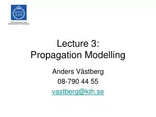
Lecture 3:Propagation Modelling Anders Västberg 08-790 44 55 vastberg@kth.se
Ionospheric propagation [Slimane]
Refraction in an ionospheric layer [Slimane]
Electron density profile [Slimane]
Cellular Networks • Network organised in cells • Each access point has a set of channels to service the users within the cell • The set of channels can be reused when the signal to interference ratio is low enough.
Macrocells • Give services in urban, suburban and rural areas. The cell radii varies from about 1 km to many tens of km. • Few users per area unit. • Base stations antennas are mounted on high buildings or on masts to get better coverage.
Microcells • In urban or suburban areas • Cell radii is approximately 500 m • Very high traffic density (many users per area unit). • Antennas mounted lower than the buildings around it to decrease the cell coverage are • More cells/unit area can services more users.
Indoor Cells (Picocells) • High data rates and high traffic densities for both mobile and fixed users • Coverage area influenced by • Layout of the building • Construction material (wood transparent to radio waves, well reinforced concrete is not). • Shape of rooms
Propagation modelling • To predict coverage areas in mobile cellular telephone systems, simple propagation models are needed. • Empirical methods • Physical models • Hybrid methods
Measurements [Saunders, 1999]
Emperical methods • Models are usually based on actual path loss measurements. • Curve fitting is used to obtain an analytical function for the model. • Parameters are given by: distance, frequency, antenna heights, distance to nearest building. • Validity of the model may be limited (dependent on the environment) • Models are practical and easy to use but not very accurate.
Physical Models • A physical model needs a very detailed description of the terrain and other clutter. • Large amount of data needed. • Excessive computational effort needed. • The important parameter for the macrocell designer is the area covered, not the field strength at particular locations.
Computerised Planning Tools • The enormous increase in the need to plan cellular systems accurately and quickly • The development of fast, affordable computing resources • The development of geographical information systems • Example: • TEMS CellPlanner, Ericsson AB
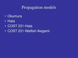
Empircal Models for Macro Cells • Power Law models • Clutter factor models • Okumura-Hata model • Cost 231-Hata Model
Plane Earth Loss [Saunders, 1999]
Physical Models for Macro Cells • Ikegami Model • Rooftop diffraction • Flat Edge model • Walfisch-Bertoni model • COST 231/Walfisch-Ikegami model
Models for Micro Cells • Dual Slope model (empirical model) • Physical Models • Two-ray model • Street canyon models • Non-line-of-sight models
Picocells • Wall and floor factor models • COST231 Multi-wall model • Ericsson model • COST 231 Line-of-sight model • Floor Gain Models • COST 231 Non-Line-of Sight model
Physical Model: Two Ray Model [Saunders, 1999]
Two-Ray Model R is the Fresnel reflection coefficient
Raytrace [Saunders, 1999]

![G3 - RADIO WAVE PROPAGATION [3 Exam Questions -- 3 Groups]](https://cdn0.slideserve.com/819386/g3-radio-wave-propagation-3-exam-questions-3-groups-dt.jpg)