Download
1 / 25
250 likes | 382 Views
This document delves into the cutting-edge research and applications of evolvable hardware systems conducted at the Jet Propulsion Laboratory (JPL). It covers the evolution of reusable systems, platforms for mixed-evolution, and the integration of adaptive filters into digital circuits. Additionally, it provides insights into the JPL EHW Testbed, hardware resources, and PGAPack for evolutionary configuration. Key highlights include performance comparisons between hardware and software evaluations, important algorithms, and the rapid evolution capabilities of the FPTA.

E N D
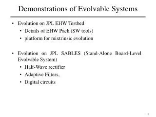
Demonstrations of Evolvable Systems • Evolution on JPL EHW Testbed • Details of EHW Pack (SW tools) • platform for mixtrinsic evolution • Evolution on JPL SABLES (Stand-Alone Board-Level Evolvable System) • Half-Wave rectifier • Adaptive Filters, • Digital circuits 1
JPL EHW Testbed Link to Hardware Evaluation Link to Software Evaluation Evolutionary Reconfiguration Mechanism (PGAPack) GUI DB LabView SW Tool: EHWPack HW resources: PC + NI HW/SW, Supercomputer A/D 256-processor machine running SPICE D/A Digital I/O Reconfigurable hardware Chips under test SW model of the HW A few minutes later the hardware has evolved (synthesized) a circuit providing the function User can draw a function using the graphical tablet 3
National Instruments Boards • PCI-DIO: digital inputs and outputs; • AT-MIO-64E board is the multipurpose board which can be used for both analog and digital inputs and outputs. • The FFT signal analyzer board is used to speed up the computation for the FFT of a desired signal. • The Image board is used to capture pictures for robot training. • The AT-AO/10 board can generate up to 10 different analog signals at the same time, which helps to reduce number of signal generators. 4
EHW Testbed details • HP Exemplar shared-memory supercomputer; • 256 CPUs and 64 GB of memory; • 16 nodes, with each node having 16 processors; • Different queues for jobs requiring different numbers of processors: 8, 16, 32 and 128; • One node dedicated to the users login session and compilation of jobs; • All the other nodes are reserved for batch jobs or interactive job requiring input-output interface with the user during execution; • The EHWPack parallel implementation uses a master/slave algorithm, in which one process, the master, executes all steps of the genetic algorithm except the function evaluations (SPICE simulation or evolvable hardware evaluation); • The function evaluations are executed by slave processors; • The master is running on one processor of the HP exemplar and the slaves are running on the other processors allocated for the job or on the FPTA hardware through an internet communication. 5
EHW Pack • Based on PGAPack • GUI • Can run Extrinsic Intrinsic & Mixtrinsic evolution • Access over Internet (e.g.by NASA Ames & NSI) • Built for easy add-on simulators/evaluators currently supports SPICE, NEMO, Diehard • New search/optimization algorithms 6
PGAPack and SW evaluation PGAPACK Parallel Genetic Algorithm Genes Parametric model Simulator SPICE NEMO Diehard Data from simulation Fitness of individual device/circuit Desired Data Graphical User Interface 1 of 256 processors Caltech supercomputer (HP Exemplar) 7
EHW Pack GUI Main Window: PGA spice.pga Parameter to Gene Mapping General Optimizer Input Parameters Submit to Queue GA Standard Parameters View Complete Queue Fitness Function Parameters TOOL SPICE3F5 GA Output/input Options 8
Differences between HW and SW evaluation • Differences between model and real HW: • Simplified models (e.g. to gain speed in SPICE runs), • Incomplete models because of lack of information about fabrication, • HW can change from the moment was modeled/identified (temperature, radiation, operating conditions), • HW can change in time after evaluation (e.g. slow discharge) • Simulator limitations (SW evaluation): • Convergence conditions, which humans may be able to help by setting/adjusting values, • Conditions unknown a-priori (e.g. charges, initial conditions), in which case the system of differential equations can not be solved • HW testing limitations: a) Transients, b) Charge, e.g. remaining from a previously evaluated individual, c) Impedance loading of measured circuit, d) Time delays between physical signals (e.g. excitatory) and outputs, e) Artifacts originating in signal generators, data acquisition paths, sampling, A/D, etc 10
Extrinsic, Intrinsic and Mixtrinsic Population of candidate solutions Population of candidate solutions Parallel Search Algorithm Parallel Search Algorithm SW1 SW2 SWn HW1 HW2 HWn ... ... Population of Software models Population of Hardware solutions Intrinsic EHW: evaluations of hardware solutions Extrinsic EHW: evaluations of software solutions Parameters Configuration Reconfigurable HW Population of candidate solutions Model Parallel Search Algorithm SW1 HW2 SWn HW evaluator testing equipment Simulator ... Stimulus Mixed Population of Software and Hardware Data file Data file a) b) Path from chromosome to behavior data file a)extrinsic and b)intrinsic Mixtrinsic EHW: evaluations of mixed populations comprised of both hardware and software solutions Portability problem... 11
HW is needed for complex circuits 10,000 times faster evolution for for circuits with ~200 transistors compared to SPICE simulations on Sun Ultra 80). The FPTA enables rapid evolution (seconds), orders of magnitude faster than in simulations. Simulations scale poorly, while HW evaluation is size independent. 12
EHW Experiments Evolutionary circuit synthesis and repair • Synthesis • Analog computational circuits (fuzzy neuron, multipliers) • Logic Circuits (XNOR, AND gates) • Filters (band-pass) • Repair: From faults and degradation with temperature 13
Programmable Transistor Array Cell Binary chromosomes used in GAs are a straightforward mapping for downloading circuits onto reconfigurable chips. Each bit of the chromosome determines the state of a switch in the reconfigurable device. 100011….1111 Simplified Cell in Field Programmable Transistor Array 14
3 2.5 2 Output (Volts) 1.5 1 0.5 0 0 1.5 3 4.5 6 7.5 9 10.5 12 Sample Step-by-step evolution example Evolve a computational circuit which responds with a Gaussian current output when the input is ramped between Gnd to Vdd.
Mapping classical circuits on FPTA V+ S1 P1 P2 S7 S12 S4 (A) S8 S5 S2 P3 P4 S3 S13 S9 S6 Out S10 S14 (B) S16 S17 S15 In+ In- S11 N5 N6 S18 S19 S21 S23 S20 N7 N8 S22 S24 Transconductance Amplifier mapped into FPTA 16
Genes and their mapping to hardware What is needed first: the “genes” representation for the system to be evolved (STBE), and the mapping/transformation from genes to an “embodiment” of the STBE. Gene representation: could be a binary word “10101100” , each bit defines the value of a 2-state device. Mapping/transformation from genes to an “embodiment” In extrinsic Evolvable Hardware the “embodiment” is a description of a model of the STBE submitted to a simulator that evaluates the model and generates a behavioral response. 1 R = 10 Turn Switch ON 0 R=10M Turn Switch OFF In intrinsic Evolvable Hardware the “embodiment” is the programmable circuit itself. 17
Template FPTA SPICE Netlist .MODEL NMOS NMOS LEVEL=8 TOX=7.6000E-09 XJ=0.100000U + VTO=0.4777253 DELTA=1.00E-02 … .MODEL PMOS PMOS LEVEL=8 TOX=7.6000E-09 XJ=0.100000U + VTO=-0.7111998 DELTA=1.00E-02 … * Basic Circuit Configuration for evolvable hardware m1 n1d n1g 1 1 PMOS l=1.2u w=1.2u m2 n2d n2g 1 1 PMOS l=1.2u w=1.2u … m7 n7d n7g 0 0 NMOS l=1.2u w=1.2u m8 n8d n8g 0 0 NMOS l=1.2u w=1.2u * the tgate-based switches m9 n1g S1 n2g 0 NMOS w=1.2u l=.6u m10 n2g _S1 n1g 1 PMOS w=3.6u l=.6u m11 n1d S2 n3s 0 NMOS w=1.2u l=.6u m12 n3s _S2 n1d 1 PMOS w=3.6u l=.6u … m55 n7g S24 n8g 0 NMOS w=1.2u l=.6u m56 n8g _S24 n7g 1 PMOS w=3.6u l=.6u vdd 1 0 DC 3.3v vin+ n5g 0 DC 1.5 vin- n6g 0 DC 1.5 .DC vin+ 0.0v 3.3v 0.15v .Print DC v(n4d) .END Field Programmable Transistor Array 10000….0001 *Resistance Based switches R1g2g 1g 2g R1_ R1d3s 1d 3s R2_ … R7g8g 7g 8g R24_ 1 means closed switch 0 means open switch Each bit of the chromosome determines the state of a switch in he reconfigurable device. 18
From chromosome to voltages (or resistances) 3.3V Switchi Biti = 1 Ri = 50 OR 0V 0V Switchi Ri=1010 OR Biti = 0 3.3V 19
Output netlist with resistances R1g2g 1g 2g 50 R1d3s 1d 3s 1e+10 R1d5d 1d 5d 1e+10 R1g1d 1g 1d 50 R2d4s 2d 4s 50 R1d6d 1d 6d 50 R3sdd 3s 1 1e+10 R3s4s 3s 4s 1e+10 R3g4g 3g 4g 50 R3d5d 3d 5d 1e+10 … R7d7g 7d 7g 1e+10 R7g8g 7g 8g 50 0 1 1 0 0 ? ? 20
Output netlist with transistors Voltages Switches vs1 S1 0 0.000000 v_s1 _S1 0 3.300000 vs2 S2 0 3.300000 v_s2 _S2 0 0.000000 … vs24 S24 0 3.300000 v_s24 _S24 0 0.000000 m9 n1g S1 n2g 0 NMOS w=1.2u l=.6u m10 n2g _S1 n1g 1 PMOS w=3.6u l=.6u m11 n1d S2 n3s 0 NMOS w=1.2u l=.6u m12 n3s _S2 n1d 1 PMOS w=3.6u l=.6u … m55 n7g S24 n8g 0 NMOS w=1.2u l=.6u m56 n8g _S24 n7g 1 PMOS w=3.6u l=.6u 21
Circuit Output Fitness = (Yi – Ti)2 i Target Actual Data Output File 0.081971 0.246255 0.605690 1.219709 2.010960 2.714512 3.000000 2.714512 2.010960 1.219709 0.605690 0.246255 0.081971 2.005E-04 7.598E-02 6.637E-01 1.556E+00 2.299E+00 2.482E+00 2.428E+00 2.252E+00 2.006E+00 1.717E+00 1.406E+00 1.102E+00 8.186E-01 vin+ V(n4d) 0.000E+00 1.828E-04 1.500E-01 1.800E-04 3.000E-01 1.773E-04 4.500E-01 1.744E-04 6.000E-01 1.708E-04 7.500E-01 1.670E-04 9.000E-01 1.630E-04 1.050E+00 1.591E-04 1.200E+00 1.552E-04 1.350E+00 1.513E-04 Target (T) Actual Data (Y) 22
Selection: Ranking Rank individuals according to the quality of their response 23
Evolutionary algorithms visualized New Population (Pop. Size 512, 24 bits) Evaluations (30 samples) Fitness (MSE) Population Compare to Target Population Initialization (Randomly) 0.10 01001110111001 Vout 0.11 0.11 Elite (10 %) 01001110110000 Vin 0.15 01001010110000 Vout Sort 0.34 • Evaluation • Simulators (SPICE) • Hardware (PTAs) 0.27 11001110111001 0.29 Vin 01011110111001 Recombined Individuals 0.10 Vout 0.34 01100010100001 0.39 Vin 01000111101000 Vout 0.53 0.53 10110111110110 Vin Binary Tournament Selection (size 2) Two Points Crossover (Prob. 70%) Uniform Mutation (Prob. 4%) Elite (10%) Elite (10%) 01001010110000 0.15 01001010110000 01001110110000 01101111110000 Recombined Individuals 0.39 01000111101000 2*2 rand Best 0.29 01011110111001 01011110111001 01011010111001 11011010011011 10110111110110 0.53 24
Results of on-chip evolutionary synthesis Board with 4 PTA chips A/D Digital I/O D/A LabView captured output of 4 circuit solutions Evolvable hardware chips under test 25