Download
1 / 21
210 likes | 414 Views
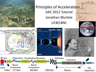
Acceleration Schemes of of Modern Electron Guns. Jochen Teichert. ULTRA BRIGHT Electron Sources Workshop 29 June – 1 July 2011, The Cockcroft Institute Daresbury. Overview. Introduction – high brightness beams Overview of modern electron guns superconducting RF photo guns

E N D
Acceleration Schemes of of Modern Electron Guns Jochen Teichert ULTRA BRIGHT Electron Sources Workshop 29 June – 1 July 2011, The Cockcroft Institute Daresbury
Overview • Introduction – high brightness beams • Overview of modern electron guns • superconducting RF photo guns • The superconducting RF photo gun at ELBE • gun acceleration gradient • emittance compensation in SC guns • messurements • ultra short pulses (idea from V. Volkov et al.) • Summary
Introduction – High Brightness Beams Definition of brightness: The electron density in 6D phase space ~ Integrating over energy spread: brightness A figure for the quality of a bunch, but not for the number of bunches/time frep Using the average: For a high mean value (light sources): high rep. rate and low bunch charge, Formula contains no bunch length: DC is the best (electron microscope).
Introduction – High Brightness Beams SRF High Brightness Electron Guns The BES Photon Workshop held on October 2009 concluded that for ultimate performance in future radiation sources MHz repetition rate is needed. The workshop also noted that the realization of such sources “is also hindered by the lack of technical developments as far as gun performance is concerned.” These recommendations lead naturally to CW operating electron guns, since no pulsed system with a sufficient stored energy can operate at MHz rates. Superconducting RF guns are one of three contenders in this arena. Statement of Workshop on Future Light Sources SLAC, 2010 ULTRA high brightness electron sources are still a challenge. Nevertheless we should think about it.
Introduction – High Brightness Beams Emittance contribution from the gun: thermal, rf field, space charge High final momentum - space charge forces scales as - ~500 keV reduces SC forces sufficiently Gradient at cathode - space charge limit: max. bunch charge - Ea > Esc preserves beam quality - shortening low energy path Thermal emitt. scales as rlaser small r <-> SC force small Ephoton <-> low QE Higher frf : higher gradient εn,x scales as tb2/λrf increasing rf-nonlinearities
The three “modern” gun types DC photo guns Normal conducting RF photo guns high frequency (≥1.3 GHz) low duty factor low frequency (≤ 800 MHz) high duty factor & cw Superconducting RF photo guns
Superconducting RF Photo Guns At present, a lot of different approaches depending on application: average current (ERL type guns), bunch charge and brightness leak of konowledge: over/under estimation of problems SRF guns with TESLA-style elliptical cavities HZDR/Rossendorf (since 1998) IHIP Peking University (since 2001) frf = 1.3 GHz NC PC: Cs2Te frf = 1.3 GHz NC PC: Cs2Te DC-SRF Photo gun BNL, Jlab, DESY (since 2002) frf = 1.3 GHz SC PC: Pb frf=1.3 GHz SC PC: Nb, Pb NC PC: GaAs BERLinPro stage one gun
Superconducting RF Photo Guns High current / low frequency cavity Quarter wave cavity NPS, NIOWAVE frf = 500 MHz SC PC: Nb Uni Wisconsin, Niowave frf = 200 MHz NC PC: Cs2Te frf = 703.75 MHz NC PC: alkali + diamond amplifier frf = 112 MHz BNL, Niowave
The superconducting RF photo gun at ELBE SRF Gun Cryomodule helium port liquid He vessel photo cathode alignment cavity tuners LASER cathode cooling (77 K) & support system e- NC Cs2Te photo cathode rf power coupler SC Nb 3½ -cell cavity
Gun accelerating gradient half cell 3 TESLA cells 2 HOM couplers cathode sc choke filter (to prevent RF leakage) FZD coupler & pickup ant. • Design values • Bs,max = 110 mT max. magn. surface field • Ecathode = 20 MV/m (backtracked cathode) • Epeak (1st cell) = 30 MV/m • Epeak (TESLA)= 50 MV/m
Gun accelerating gradient Performance of HZDR´s first 3.5 cell cavity (3.5cell/2006) vertical tests @ DESY, 1.8 K measurements in gun 2007 -2011 risk of contamination due to the NC photo cathode? After > 1000 h operation no deterioration was seen. The insufficient cleaning (HPR) was the major problem – esp. choke filter & half-cell
Gun accelerating gradient Gradient in elliptical1.3 GHz gun cavities: The challenge is the field in TESLA (Flash, XFEL, ILC) cavities DESY vertical testcryostat D. Reschke, et al. SRF´09, Berlin DESY horizontal CW test D. Kostin, et al. SRF´09, Berlin
Gun accelerating gradient Since gun performance mainly depends on gradient, Ea≈ 60 MV/m will give emittance < 1 µm @ 1 nC + shaped laser + emittance compensation needed (see PITZ gun) vertical cryostat P. Kneisel 3.5 cell /2010FG fine grain RRR 300 Nb 3.5 cell/2010LG large grain Nb
Gun accelerating gradient Naval Postgraduate School (NPS) 500 MHz quarter wave resonator First beam in 2010: beam energy: 480 keV peak field: 8.5 MV/m Advantages of quarter wave resonators: low frequency and small size DC like field in the gap > high transit time factor, longer pulses low rf losses allow 4.2 K operation low rf losses at the cathode Drawback comp. to elliptical cavities: no multi cell design
Emittance compensation methods Down stream solenoid focusing Retracted or shaped cathode better : SC solenoid in cryostat NPS & HZB Additionally excited TE mode Solenoid field like axial field
C2 energy chirp energy spectrum bunch length vertical quadrupole scan energy width correlation SRF gun injection in ELBE for advanced beam diagnostic • Phase scan technique for • longitudinal phase phase • Slice emittance measurement
fs bunches from the gun Bunch compression by means of “wrong” laser phase
fs bunches from the gun kinetic energy & energy spread SRF gun phase scan – optimum laser phase ? screen DV02 (YAG) 1.9 m from gun exit, 2.7 m from cathode -175°, σx = 300 µm +3°, σx = 1650 µm -150°, σx = 330 µm -130°, σx = 610 µm -115°, σx = 760 µm -95°, σx = 330 µm -65°, σx = 430 µm
fs bunches from the gun ASTRA simulation, 1.5-cell gun, 15 MV/m peak field looping in half-cell experimental verification still needed: energy width, emittance, bunch length
Photoelectron injectors for high-brightness beams and cw operation *) design values 1) F. Sannibale, et al., Proc. of FEL´20, Malmö, Sweden, 2010, p. 475. 2) J.R. Harris, et al., Phys Rev. ST AB 14, 053501 (2011). 3) A. Arnold, et al., NIM A 577, 440 (2007). 4) N. Nishimori, et al., Proc. of LINAC´10, Tsukuba, Japan, 2010, p.995.
Thank you for your attention The ELBE Crew visiting the German Watch Museum Glashütte/Sa. December 2010 Thanks to my colleagues at ELBE and all collaborators. Apologies for the “stolen” pictures in the talk.