Download
1 / 39
390 likes | 538 Views
Readiness Report on T1 Electrical Systems and Electronics. Summary. Readiness of all systems Response on change requests from ESR in September QA/QC, including test during and after installation with requests of necessary infrastructure. Overview of T1 detector. T1 is composed by 2 arms

E N D
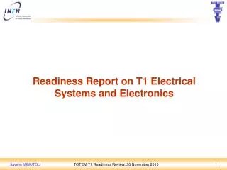
Readiness Report on T1 Electrical Systems and Electronics TOTEM T1 Readiness Review, 30 November 2010
Summary • Readiness of all systems • Response on change requests from ESR in September • QA/QC, including test during and after installation with requests of necessary infrastructure TOTEM T1 Readiness Review, 30 November 2010
Overview of T1 detector • T1 is composed by 2 arms • Each arm is composed by 5 planes • Each plane is composed by 6 CSC trapezoidal chambers • Each chamber is composed by 1 anode and 2 cathode planes • For mechanical reasons, each arm is divided into two halves : each half is considered independent from the other also from electrical/logical point of view • In total, each halve include 15 chambers TOTEM T1 Readiness Review, 30 November 2010
T1 detector in H8 TOTEM T1 Readiness Review, 30 November 2010
S-bit DataOut Clk40 FastCmd I2C • T1 functionalelectronics system architecture Local Detector region Counting Room region On Detector region TOTFED TOTFED LVDS CMOS TDAV MUX GOHs Trigger Info OPTORx Trigger bits CSC Detectors AFECs CFECs Readout Path LVDS CMOS DDAV MUX GOH OPTORx Data bits VFAT OPTORx TTCRx Data to DAQ (S-Link; VME; or USB) ROC SPY Mezz VFAT TrgMez DOHM FEC CCUM Control Path DOHs mFEC CLK40 Tree QPLL TokenRing VFAT PLL25 40÷100 cm TTC DCU CMOS LVDS T1 Tree TTCRx TOTEM Slow Control 4 x 15 Det 4 x 15 AFEC + 4 x 39 CFEC 4 x 9 ROC 4 x 1 DOHM 2T + 2D + 4mFEC = 4 x T1 ¼ TOTEM T1 Readiness Review, 30 November 2010
¼ T1 electronic boards placement = CSC 6th frame ROCs 45 = ROC C A ROCs 23 5 T C A 4 ROCs 01 = DOHM C A 3 T 5 C C M = CFEC 4 A C T 2 C C DOHM 3 A 1 A M = AFEC 5 C 2 A M 4 C 1 C A 3 B C A 2 C A A A 1 B = IP5 C B C A A A TOTEM T1 Readiness Review, 30 November 2010
¼ T1 at the CERN lab. B188 TOTEM T1 Readiness Review, 30 November 2010
Summary • Readiness of all systems • Response on change requests from ESR in September • QA/QC, including test during and after installation with requests of necessary infrastructure TOTEM T1 Readiness Review, 30 November 2010
MARATON Primary Rectifier MARATON Remote Controller -N -F +N +F -n -f +n +f Control Room T1 Low Voltage system 2 x 4 ; 36 wires shielded cables, to MARATON Power Box ¼ T1 ¼ T1 - MARATON Power Box Distribution Box 6° frame Distribution Box 6° frame MARATON Power Box FUSE Box FUSE Box Vense Box Vsense Box Far Near On platform On platform On platform Vense Box Vsense Box FUSE Box FUSE Box MARATON Power Box MARATON Power Box Distribution Box 6° frame Distribution Box 6° frame + ¼ T1 ¼ T1 TOTEM T1 Readiness Review, 30 November 2010 Saverio MINUTOLI 9
LV OPFCs electrical connections • Each T1 quarter is powered independently. • 4 electro-mechanic breakers installed • Tested and deployed within DSS. • Electrical drawing updated • OPFCs AC input and DC output tested • 3 OPFCs already installed • 4th currently used in H8 • 1 OPFC spare at the B188 (electronic boards test bench). • 385V DC connections tested on both sides (rack and platform). TOTEM T1 Readiness Review, 30 November 2010
T1 services rack on HF platform • 4 minirack installed on HF platform • Safety smoke turbine installed, connection to DCS ?? • All cables from the Counting Room traced and tested • Cooling circuit done on –side, +side ?? TOTEM T1 Readiness Review, 30 November 2010
MARATON power box • 3 MARATONs already installed • 4th currently used in H8 • 1 spare at the B188 (electronic boards test bench) • MARATON local settings adjusted • Vout=2.5V; Imax=15A; OVP=4V. • All MARATONs on the platform even the empty location, switched ON and controlled from CR via Remote Control Monitoring boards and OPFCs. • 3 RCMs already installed • 4th currently used in H8 • 1 spare at the B188 (electronic boards test bench) • All RCMs and cabling to MARATON have been tested. HF PLATFORM TOTEM T1 Readiness Review, 30 November 2010
¼ T1 Local L.V. distribution • Local LV distribution completely redesigned (ESR request). • Built Fuse Box on platform • Built an integrated Fuse Box monitoring system DCS • Built new LV cables, between HF platform and 6th frame of T1 • Built new T1 6th frame internal LV distribution Box • Modified internal T1 LV cabling • Replaced internal LV connectors • Modified internal LV sense distribution • Built Vsense Box on platform • All of the items above have been checked and tested in the last test beam in H8 • Because of this renewal of the system, need to replace the cables minus side On platform ¼ T1 MARATON Power Box Distribution Box 6° frame FUSE Box Vsense Box Cable path way. TOTEM T1 Readiness Review, 30 November 2010
T1 H.V. system DCS SCADA OPC Server 4 x A1550P HV modules R.M.= 52 pin Radiall Connector ¼ T1 ¼ T1 - R.M. Distribution box on 6th frame Distribution box on 6th frame R.M. SHV SHV Far Near R.M. R.M. SHV SHV Distribution box on 6th frame Distribution box on 6th frame A1550P 24 Chs 5 kV/1mA + ¼ T1 ¼ T1 TOTEM T1 Readiness Review, 30 November 2010
H.V. distribution • HV Main frame in CR shared between all TOTEM subdetectors • 3 modules A1550P already installed • 4th currently used in H8 • 1 spare at the B188, ready to be installed • All HV boards have been tested • Checked the Safety interlock of the local HV distribution box. • All the HV cabling between CR and Platform have been tested, even with ¼ T1 emulator with dummy load. TOTEM T1 Readiness Review, 30 November 2010
Slow Control Ring system 6th frame ROCs 45 = CSC ROCs 23 5 0x7E 4 ROCs 01 = ROC 3 0x77 5 0x7D 4 • 0x78 = DOHM 2 DOHM 3 1 0x76 5 = SCR cable 2 0x79 4 1 3 0x7C 2 1 0x7B = IP5 0x7A • SCR distributes Fast Command (L1, BC0, Calib, Reset) and LHC clock • Manage the F.E. settings through 16 I2C channels. • DOHM independent LV channel • Redundancy connection checked • All the ¼ T1 quarters passed the SCR tests. TOTEM T1 Readiness Review, 30 November 2010
¼ T1 Optic System 6th Frame Fan-out Box on T1 6th frame Control Room Platform GOL/DOHM Optic Fibers Patch Panel 8 MPO 3m 12 3m GOL/DOHM #1 Data ¼ T1 internal distribution 1m 4.5m SCR #2 100m Multi ribbon cable (8x12) Trigger #3 Ribbon fiber cable (12x1) Single fiber Trigger #4 MPO in line adapter TOTEM T1 Readiness Review, 30 November 2010
Optic fibers distribution • Patch panel in Control Room installed • Control Room Fiber patch cords available • FEC, Data TOFED and Trigger TOTFED • Local patch cords between Platform and T1 6th frame available • T1 internal connections checked and tested • All T1 (4 x ¼) fiber optic systems have tested and validated during last test beam in H8 • Local patch cords need to be installed on YE3 disk. TOTEM T1 Readiness Review, 30 November 2010
¼ T1 DCS and DSS systems • DCS system • 3 PT100 temperature sensors installed and checked • 2 on electronic boards and 1 on cooling plate • 2 active Radiation Monitor sensors installed and checked • 1 on 1st plane internal and 1 on 5th plane external • On the adjacent quarter the RadMon sensors are located on the same plane but opposite sides. • DSS system • 2 PT100 temperature sensors installed and checked • 2 on electronic boards. • 2 passive Radiation Monitor sensors installed TOTEM T1 Readiness Review, 30 November 2010
T1 DCS and DSS systems • Each DCS/DSS system of ¼ T1 have been checked and tested. • DCS and DSS systems (both hardware and software) of T1 tested for 4 quarters during last short technical stops using a special unit to simulate the T1 presence. • T1 DCS box in the Counting Room • Temporally removed to include the LV Fuse monitoring • All the cables DCS, DSS and Spares. RADMON PT100 TOTEM T1 Readiness Review, 30 November 2010
Other sensors • Sensors (position x, y, z) (Joao): • Ultra sound sensors mounted, cabled and tested • Potentiometers mounted, cabled and tested • The position of the Potentiometer sensors must ensure the exchangeability of the quarters. • B Sensors (Benoit): • Only 8 out of 16 sensors installed (¼ yellow and ¼ green). • cabling of B sensors to be completed TOTEM T1 Readiness Review, 30 November 2010
Alignment laser beams system • Alignment system of CMS traversing T1: • Checked all cables for possible interference • Mechanical fixation to keep cables from entering laser beam zone TOTEM T1 Readiness Review, 30 November 2010
Grounding and Shielding systems • Shielding of the digital signal cables completed • Reinforced electrical connection of Aluminum structure parts • Earthing point on CMS finalized (Sergei and Dmitry) Main grounding ribbon running the length of the support frame TOTEM T1 Readiness Review, 30 November 2010
Summary • Readiness of all systems • Response on change requests from ESR in September • QA/QC, including test during and after installation with requests of necessary infrastructure TOTEM T1 Readiness Review, 30 November 2010
Requests (1) • The committee recommends contacting the CMS integration office for a ground point onto YE2, YE3, and perhaps onto the HF platform. Dmitry should be involved since this is rather a mechanical issue. • I propose to drill the threaded holes on inner radial surface of "YE4 inner disks" with 30 mm offset from its edge. The holes should be on 3 o'clock and 9 o'clock for both EndCaps. (Dmitry) • Each ¼ T1 have a main grounding ribbon running the length of the support frame. The ribbon is copper, 200 microns thick and approximately 10 cm wide. (also by Sergei) • Exteriors of CSCs connected with copper foil (also by Sergei) • In addition the aluminum support structure electrical continuity have been reinforced with copper braid or thick wires. TOTEM T1 Readiness Review, 30 November 2010
Requests (1) Cavern GROUND Main grounding ribbon Boards support grounding CSC ground reinforced Frame joints reinforced TOTEM T1 Readiness Review, 30 November 2010
Requests (2) • The committee endorses the insertion of fuses to protect 1.5mm2 power cables between the LV power supply and the 6th frame. It is important to explore the failure modes with the inline fuses in conjunction with remote sensing. Consider to add remote monitoring of the fuses for trouble shooting. Make sure that any additional work on the – side gets into the site planning. • Request of installing fuses on each electronics card triggered a complete redesign of the LV distribution on the detector. • Two x 4 LV distribution boxes (on T1 and at the MARATON output) • New cables on YE3 to connect the LV boxes • One fuse on each line at the MARATON output. Status of fuses is available locally and remotely through DCS. • One x 4 LVsense box (at the MARATON input) • Additional work on –side already planned within the schedule. TOTEM T1 Readiness Review, 30 November 2010
Requests (2) “Panels and Cables” ¼ T1 internal LV and Vsense cabling New 6th frame LV Distribution Box Fuse Box Front view Fuse Box Rear view New LV cables TOTEM T1 Readiness Review, 30 November 2010
Requests (2) “Remote monitoring” All ROC Fuses OK Fuse ROC_TOP blown ROCs 2V5 Main power OFF • By means of an optoMOS, the information on the status of each of the fuses is stored in digital format, optically isolated from the DCS system. The three fuse status bits for each ROC plane, plus the ON/OFF status of the main voltage, are fed to an R-2R ladder network. DOHM Fuse OK Fuse DOHM blown DOHM 2V5 Main power OFF TOTEM T1 Readiness Review, 30 November 2010
Requests (2) “Vsense redundancy” Vsense Box Added Low Voltage sense redundancy in order to avoid Slow Control Ring break due to the master ROC failure. TOTEM T1 Readiness Review, 30 November 2010
Requests (2) “Vsense behavior in failure mode” OVP = 3.3V OVP = 2.9V OVP = 4V TOTEM T1 Readiness Review, 30 November 2010
Requests (2) “Vsense behavior in failure mode” Can be forced to zero by SW 5ms. TOTEM T1 Readiness Review, 30 November 2010
Requests (3) • Verify with the manufacturer that the flat cable crimp quality is qualified for power distribution of the foreseen levels. • The CSORVEM company (www.csorvem.it ISO9001) has confirmed that all its products are tested both mechanically and electrically within the limits of the characteristics of the components. • Automatic and semi-automatic crimping machines and more than 40 different tools/die sets available. • In our case Dielectric strength contact to contact of 500V and Current rating of 1.2A@20˚C for the Erni SMC type B connector. • In our case Voltage rating of 50V and Current rating of 300mA considering a section of wire 0.050mm2 (6A@1mm2) for the flat cable. • The manufacturer confirms that the crimp quality is qualified for power distribution of the foreseen levels. TOTEM T1 Readiness Review, 30 November 2010
Requests (3) ISO 9001 Quality test TOTEM T1 Readiness Review, 30 November 2010
Requests (4) • The Committee endorses the plan for shielding of the flat cables to the chambers. • All digital flat cables were removed from the detector and shielded with copper tape (35μm) welded at its overlapped ends. • The shield was protected by an insulation braid. • The shield was connected to the metallic cover of the ROC (source) by means of wire soldered to the cable shield on one side and a terminal lug to the other. Shielded cables TOTEM T1 Readiness Review, 30 November 2010
Summary • Readiness of all systems • Response on change requests from ESR in September • QA/QC, including test during and after installation with requests of necessary infrastructure TOTEM T1 Readiness Review, 30 November 2010
Installation test and infrastructure • CHECKS on the system are foreseen when in the cavern • They are programmed in the last phases of installation: • Before insertion in the end cap • After the insertion in the end cap and before moving HF on 4 risers • The system check needs the LV, HV, R/O and DCS/DSS connections. • This in turns requires: • DCS running • Power for LV racks • S4 F05 (rectifiers) EXD 20/55 (breakers) • Power in TOTEM racks • S2 B03 (HV) S2 B02 (DCS) • DAQ-Data DAQ-Trigger TOTEM T1 Readiness Review, 30 November 2010
Installation test and infrastructure • Schedule and assignment of manpower finalized • Presence of key people from CMS and TOTEM for the installation is defined. • Availability of manpower confirmed : CERN, INFN, and availability of FSU • The work to be completed before installation is on schedule TOTEM T1 Readiness Review, 30 November 2010
Conclusions • Commissioning of the 4 quarters had been extensively done on the H8 beam in the past months. • Both hardware and software checked and functional. • Transport of 2 quarters to IP5 planned for the beginning of December (7-10) • The other two quarters will preferably be transported beginning of January (7-8) We are ready for installation Thank you for your attention. TOTEM T1 Readiness Review, 30 November 2010


![Market Research Report on Electrical and Electronics Retailing in South Africa [2019]](https://cdn4.slideserve.com/7281321/slide1-dt.jpg)