Download
1 / 26
270 likes | 383 Views
Study on mitigating radiation damage in reactor pressure vessel walls, experimental approach, neutron field evaluation, specimen analysis.

E N D
ATTENUATION OF RADIATION DAMAGEAND NEUTRON FIELD IN RPV WALL(Plans and preliminary results) Milan Brumovsky, Milos Kytka, Milan Marek, Petr Novosad V.N.Golovanov, V.V.Lichadeev, V.M.Raetsky, A.L.Petelin, V.N.Lyssakov Author: M.Brumovský
IAEA TECHNICAL CO-OPERATION PROJECT CO-ORDINATOR : NUCLEAR RESEARCH INSTITUTE REZ plc IRRADIATION REALISATION : RIAR, DIMITROVGRAD TESTING SPECIMENS : NUCLEAR RESEARCH INSTITUTE REZ plc RIAR, DIMITROVGRAD PROJECT ANALYSIS AND EVALUATION: NUCLEAR RESEARCH INSTITUTE REZ plc Author: M.Brumovský
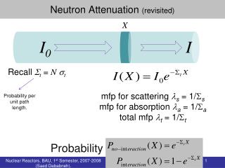
PURPOSE OF THE EXPERIMENT • Radiation damage in reactor pressure vessel wall (RPV) is usually determined on the basis of neutron field calculations and experiments from surveillance specimen programme testing. However, it is known that neutron spectrum is changing through the RPV wall but no direct correlation exist between neutron damage and neutron spectrum. • Thus, real radiation damage through RPV wall can be determined by a large scale experiment of mock-up type only where changes in material properties through the vessel wall are determined and connected simultaneously with changes in neutron field in specimens locations. Author: M.Brumovský
TECHNICAL SPECIFICATION OF THE EXPERIMENT • Neutron fluence on inner mock-up surface – approx. 6 x 10²³ m-2 (En larger than 0.5 MeV), (approx.4 x 1023 m-2 (En larger than 1 MeV), in the location of test specimens (i.e. in one specimen layer) the maximum difference should not be larger than 15 % in neutron flux between layer centre and layer sides/boundaries • Irradiation temperature – 288 +/- 10 °C throughout whole specimen block Author: M.Brumovský
NEUTRON DOSIMETRY • Neutron dosimetry should be assured to characterise neutron field (fluence and spectrum) in the whole specimens block in all three directions. TEMPERATURE MEASUREMENTSTemperature through the specimens block should be realised by a set of thermocouples located in typical locations – outer surfaces as well as in the block centre. Temperature should be continuously measured and in agreed time intervals recorded. Author: M.Brumovský
IRRADIATED SPECIMENS • WWER-1000 • BASE METAL : • SPECIMENS FROM MIDDLE HALF OF THICKNESS (I.E. ACCORDING TO ACCEPTANCE TESTS) • SPECIMENS FROM ALL LAYERS OF THE WHOLE THICKNESS • WELD METAL • IAEA REFERENCE STEEL JRQ • SPECIMENS FROM MIDDLE HALF OF THICKNESS (I.E. ACCORDING TO ACCEPTANCE TESTS) • SPECIMENS FROM ALL LAYERS OF THE WHOLE THICKNESS • PWR RPV MATERIALS • BASE METAL • WELD METAL Author: M.Brumovský
TYPE OF SPECIMENS -Charpy V-notch impact specimens -Pre-cracked Charpy size static fracture toughness specimens -Instrumented hardness specimens (for determination of tensile properties) • TOGETHER 809 IRRADIATED SPECIMENS Author: M.Brumovský
IRRADIATION • IRRADIATION WAS PERFORMED IN NIIAR – REACTOR RBT-6 • IRRADIATION FACILITY „KORPUS“ • IRRADIATION IN CYCLES • NEUTRON FLUENCE ON THE FIRST LAYER (7 – 8) x 1023 m-2 (E > 0.5 MeV) • MEAN IRRADIATION TEMPERATURE • (286 6) OC Author: M.Brumovský
IRRADIATION ASSEMBLY „KORPUS“ORIGINAL DESIGN Author: M.Brumovský
REAL IRRADIATIONS • TWO IRRADIATION CAPSULES: • CZR-1 AND CZR-2 • IRRADIATION CAPSULE: • 2 IRRADIATION BLOCKS • IRRADIATION BLOCK: • 18 LAYERS • EITHER 9 CHARPY-SIZE SPECIMENS • OR UP TO 36 INSERTS (10X10X13.75 mm) Author: M.Brumovský
CONFIGURATION OF THE EXPERIMENT Author: M.Brumovský
NEUTRON MONITORS • Assembling of 120 capsules with 600 NRI fluence monitors and 600 RIAR monitors, their installation into the plates of the ampoule • Neutron fluence monitors are installed in plates under block B, between blocks B and C and above block C. The capsules also contain RIAR monitors Author: M.Brumovský
Capsules location in the holes of monitor plates No.2, 3, 4. Author: M.Brumovský
TEMPERATURE MEASAUREMENT Installation of 72 thermocouples: Specimens of block B are installed on the second layer of the ampoule, and specimens of block C – on the third layer. On the 1st and 4th layers there are simulators. Location of the specimens in blocks B and C corresponds to the diagram proposed by NRI. The notches of Charpy specimens view the reactor core. Author: M.Brumovský
LOCATION OF THERMOCOUPLES Author: M.Brumovský
REAL IRRADIATIONS • EXPERIMENT CZR- 1 (BLOCKS B + C) • BLOCK B: • 15Kh2NMFAA-BM – ¼ OF THICKNESS • 15Kh2NMFAA-WM • BOTH IN 5 DEPTHS • IAEA JRQ as reference – ¼ OF THICKNESS • BLOCK C: • ASTM A 533-B – BM • ASTM A 533-B – WM • BOTH IN 5 DEPTHS • IAEA JRQ as reference – ¼ OF THICKNESS Author: M.Brumovský
Temperature change over thickness of samples blocks B (1,2) and C (3,4,5). 1, 4 - Charpy samples with index J, 2, 5 - samples with other indices and, 3 - Charpy samples with index A; 6 - average irradiating temperature value, 7 и 8 - bounds of the range 280<Т<290 0С. Author: M.Brumovský
REAL IRRADIATIONS • EXPERIMENT CZR- 2 (BLOCKS A + D) • BLOCK A: • 15Kh2NMFAA-BM – THROUGH THICKNESS • IAEA JRQ as reference – ¼ OF THICKNESS • BLOCK D: • IAEA JRQ – THROUGH THICKNESS • IAEA IRQ – 1/4 OF THICKNESS Author: M.Brumovský
Temperature change over thickness of sample blocks A (1,2) and D (3,4). 1 - samples with index A, 2 - samples with index R, 3 - samples wth index J, 4 - samples with index R; 5 - average irradiating temperature value, 6 and 7 - bounds of the range 280<Т<290 0С. Author: M.Brumovský
COMPARISON OF NEUTRON FLUENCES IN BOTH EXPERIMENTS Author: M.Brumovský
COMPARISON OF NEUTRON FLUENCES WITH DIFFERENT NEUTRON ENERGIES Author: M.Brumovský
SPECTRAL INDEXES Author: M.Brumovský
TRANSITION TEMPERATURES OF JRQ STEEL Author: M.Brumovský
TYPICAL CHARPY CURVE Author: M.Brumovský
PRELIMINARY CONCLUSIONS • IRRADIATION EXPERIMENTS PERFORMED SUCCESSFULLY • TARGET NEUTRON FLUENCE AND IRRADIATION TEMPERATURES REACHED • PRELIMINARY DISTRIBUTION OF NEUTRON FLUENCES AND ENERGY SPECTRA OBTAINED • SOME DISCREPANCIES WITH RG 1.99 FOUND • DETAILED NEUTRON SPECTROSCOPY AND CALCULATIONS IN PROGRESS - WILL BE FINISHED TILL 12/2005 • MECHANICAL TESTING IN PROGRESS – PLANNED TO BE FINISHED TILL 12/2006 Author: M.Brumovský