Download
1 / 33
330 likes | 331 Views
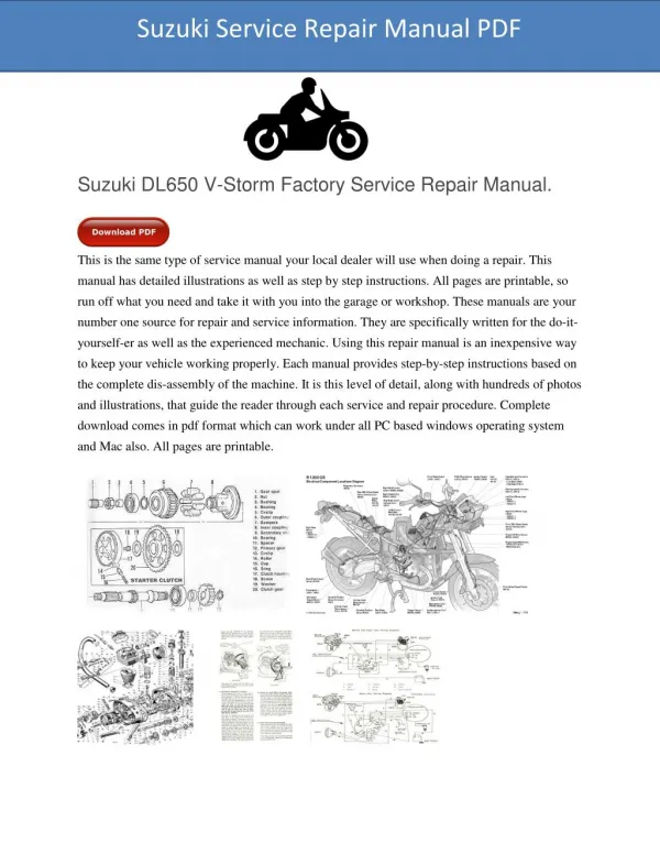
Service Repair Manual

E N D
?????????????????????????????????????????????????????????????????????????????????????????????????????????????????????????????????????? ?????????? ?!"?#????????$$?? ???#???%???!??!?????#"???????? ??????! &"?’???’ ?()*+?,-??,??+???????,*. +?? $ +??/?+ Workshop Manual.....................................................................................................2002 Workshop Manual (6195 CVT).................................................................................2002A 6-51250 6-93080 ? -.+*??0??+ Functional description Injection System...................................................................3001 Functional description Injection System - Common Rail System (6195 CVT)..........3001A 6-51300 6-93150 ? +*+??1/?(* Functional description CAN Bus (Basics).................................................................4002 Functional description and Troubleshooting – ADIC................................................4003 Function diagrams - Electrics...................................................................................4008 Function diagrams - Electrics (6195 CVT)................................................................4008A Connectors, Wiring Harnesses, Electrical and Electronic Components...................4009 Connectors, Wiring Harnesses, Electrical and Electronic Components (6195 CVT)4009A Circuit diagram .........................................................................................................4010 Circuit diagram (6195 CVT)......................................................................................4010A 6-51350 6-91700 6-92771 6-93221 6-92970 6-93290 6-51402 6-93360 ?()*+?,-??,??+???????,*. +?$ ? +*+??1/?(* Fault codes...............................................................................................................4011 6-52632 ?()*+?,-??,??+???????,*. +?? ? ??++1/????0??+ Functional description, Troubleshooting and Settings Front Axle with Independent Suspension 20.25S.....................................................5001 Functional description, Troubleshooting and Settings Front Axle with Independent Suspension 20.29S.....................................................5002 Workshop Manual - Front Axle - Carraro 20.25, 20.25 FR.......................................5005 Workshop Manual - Independently Suspended Front Axle 20.25S and 20.25SI FR5006 Workshop Manual - Independently Suspended Front Axle 20.29SI / FR.................5007 6-51450 6-51500 6-51550 6-51600 6-51651 ? ?1(?? /??/,? Functional description Transmission ........................................................................6001 Troubleshooting - System hydraulics .......................................................................6002 Cartridge - Removing and Fitting..............................................................................6005 Cartridge - Disassembling and Assembling..............................................................6006 Rear Axle - Removing and Fitting.............................................................................6007 Rear Axle - Disassembling and Assembling.............................................................6008 Parking Interlock, 4-wheel Drive Clutch and Bevel Pinion (Rear Module)................6009 6-51700 6-51750 6-51800 6-51850 6-51900 6-51950 6-52000 ??????????????????? Copyright © 2006 CNH Österreich GmbH Sva 6-52245 July 2006
2 ?031(.*/???0??+ Functional description CC-LS Hydraulic System (Closed Center-Load Sensing).... 8001 Functional description and troubleshooting High Pressure Hydraulic Circuit............................................................................... 8002 Functional description and troubleshooting (Electronic 3-point hitch control system EDC) ......................................................... 8005 Fault codes and fault description, EHS Auxiliary Control Units ............................... 8006 6-52051 6-92610 6-52100 6-52150 ? ?()/? Functional description and troubleshooting Air Conditioning................................... 9002 6-92840 Sva 6-52245 July 2006
?????????????????????????????????????????????????????????????????????????????????????????????????????????????????????????????????????? ?????????? ?!"?#????????$$?? ?()*+?,-??,??+???????,*. +?$ ? +*+??1/?(* Fault codes.............................................................................................................. 4011 6-52632 Sva 6-52245 July 2006
?????????????????????????????????????????????????????????????????????????????????????????????????????????????????????????????????????? ?????????? ?!"?#????????$$?? ?()*+?,-??,??+???????,*. +?? ? ??++1/????0??+ Functional description, Troubleshooting and Settings Front Axle with Independent Suspension 20.25S.................................................... 5001 Functional description, Troubleshooting and Settings Front Axle with Independent Suspension 20.29S.................................................... 5002 Workshop Manual - Front Axle - Carraro 20.25, 20.25 FR...................................... 5005 Workshop Manual - Independently Suspended Front Axle 20.25S and 20.25SI FR5006 Workshop Manual - Independently Suspended Front Axle 20.29SI / FR................ 5007 6-51450 6-51500 6-51550 6-51600 6-51651 ? ?1(?? /??/,? Functional description Transmission ....................................................................... 6001 Troubleshooting - System hydraulics....................................................................... 6002 Cartridge - Removing and Fitting............................................................................. 6005 Cartridge - Disassembling and Assembling............................................................. 6006 Rear Axle - Removing and Fitting............................................................................ 6007 Rear Axle - Disassembling and Assembling............................................................ 6008 Parking Interlock, 4-wheel Drive Clutch and Bevel Pinion (Rear Module)............... 6009 6-51700 6-51750 6-51800 6-51850 6-51900 6-51950 6-52000 2 ?031(.*/???0??+ Functional description CC-LS Hydraulic System (Closed Center-Load Sensing) ... 8001 Functional description and troubleshooting High Pressure Hydraulic Circuit............................................................................... 8002 Functional description and troubleshooting (Electronic 3-point hitch control system EDC) ......................................................... 8005 Fault codes and fault description, EHS Auxiliary Control Units ............................... 8006 6-52051 6-92610 6-52100 6-52150 ? ?()/? Functional description and troubleshooting Air Conditioning................................... 9002 6-92840 Sva 6-52245 July 2006
Chapter 2002 2002 ENGINE WORKSHOP MANUAL CNH Österreich GmbH Technical Documentation A – 4300 St. Valentin, Steyrer Straße 32 Sva 6-51250 EN © 2003 CNH Österreich GmbH July 2003
2002-2 TABLE OF CONTENTS SPECIAL TOOLS .....................................................................................................................5 FOR THE USER ......................................................................................................................7 Engine code and serial number ...........................................................................................7 SAFETY REGULATIONS ........................................................................................................8 ENGINE DATA .........................................................................................................................9 Lifting the engine .................................................................................................................9 TECHNICAL DATA ................................................................................................................10 Conformance with exhaust standards ...............................................................................10 Cylinder block ....................................................................................................................10 Cylinder liners ....................................................................................................................10 Cylinder head .....................................................................................................................10 Valves, rocker arms and push rods ...................................................................................11 Camshaft ...........................................................................................................................12 Crankshaft .........................................................................................................................12 Flywheel .............................................................................................................................13 Gear drive, camshaft and injection pump ..........................................................................13 Con-rods ............................................................................................................................13 Pistons, piston rings and piston pins .................................................................................14 Lubrication system .............................................................................................................14 Lubrication oil pump ...........................................................................................................15 Thermostat .........................................................................................................................15 Coolant temperature indication and monitoring (signal from sensor B22) .........................15 Coolant pump ....................................................................................................................15 Schwitzer turbocharger S200 ............................................................................................15 Tightening torques .............................................................................................................16 CONSTRUCTION ..................................................................................................................17 General ..............................................................................................................................17 Cylinder block ....................................................................................................................17 Flywheel casing .................................................................................................................17 Cylinder head .....................................................................................................................18 Valve mechanism ..............................................................................................................18 Crankshaft drive .................................................................................................................20 Timing gears ......................................................................................................................21 Lubrication system .............................................................................................................22 Cooling system ..................................................................................................................23 Fan .....................................................................................................................................24 Intake/exhaust system .......................................................................................................25 Sva 6-51250 EN Edition 07/2003
2002-3 ELECTRONIC ENGINE CONTROL SYSTEM – EEM2 .........................................................26 Layout ................................................................................................................................27 Signals ...............................................................................................................................28 Function .............................................................................................................................28 JOB INSTRUCTIONS ............................................................................................................29 1. Cylinder block ................................................................................................................29 A. Measuring the cylinder liner wear ..............................................................................29 B. Removing the cylinder liner .......................................................................................29 C. Checking the cylinder block ......................................................................................29 D. Replacing the camshaft bearing bush .......................................................................29 E. Oversize bearing bushes for the camshaft ................................................................30 F. Fitting the plug at the rear camshaft end ...................................................................31 G. Fitting the plug at the rear camshaft end after inserting an oversize bearing bush ..31 H. Installing the oil dipstick tube ....................................................................................31 I. Fitting the cylinder liner ...............................................................................................31 2. Flywheel casing .............................................................................................................33 A. Fitting the flywheel casing .........................................................................................33 B. Replacing the rear crankshaft sealing ring ................................................................33 3. Cylinder head .................................................................................................................34 A. Removing the cylinder head ......................................................................................34 B. Removing the valves .................................................................................................34 C. Checking the cylinder head .......................................................................................34 D. Replacing the valve guides .......................................................................................35 E. Machining the valve seat ...........................................................................................36 F. Replacing the valve seat rings ...................................................................................36 G. Grinding the valves ...................................................................................................36 H. Fitting the valves .......................................................................................................37 I. Fitting the cylinder head ..............................................................................................37 4. Valve mechanism ...........................................................................................................38 A. Maintenance of the rocker arm system .....................................................................38 B. Replacing the camshaft/camshaft gear wheel ...........................................................38 C. Checking and adjusting the valve clearance .............................................................39 5. Crankshaft ......................................................................................................................40 A. Removing the crankshaft ...........................................................................................40 B. Checking the crankshaft ............................................................................................40 C. Replacing the crankshaft gear wheels ......................................................................40 D. Fitting the crankshaft .................................................................................................41 E. Crankshaft hub ..........................................................................................................41 F. Replacing the crankshaft belt pulley and the vibration damper .................................42 G. Checking the rubber element in the vibration damper ..............................................42 6. Pistons and con-rods .....................................................................................................43 A. Removing the pistons together with the con-rods .....................................................43 B. Checking and replacing the con-rod bearings ...........................................................43 C. Checking the con-rod ................................................................................................43 D. Checking and replacing the piston rings ...................................................................44 E. Checking the pistons .................................................................................................45 F. Fitting the piston pin ..................................................................................................45 G. Fitting the pistons and con-rods ................................................................................45 Sva 6-51250 EN Edition 07/2003
2002-4 7. Flywheel .........................................................................................................................46 A. Replacing the starter ring gear on the flywheel .........................................................46 B. Fitting the flywheel ....................................................................................................46 8. Timing mechanism .........................................................................................................47 A. Removing the timing gear case .................................................................................47 B. Replacing the intermediate gear wheel bearing bush ...............................................47 C. Fitting the timing gear case .......................................................................................48 9. Lubrication system .........................................................................................................50 A. Checking the oil pressure valve ................................................................................50 B. Removing and checking the oil pump .......................................................................50 C. Assembling and fitting the oil pump ..........................................................................50 D. Fitting the sump ........................................................................................................51 E. Oil cooler ...................................................................................................................51 F. Piston cooling nozzles ...............................................................................................52 G. Recommended lubrication oils ..................................................................................52 10. Cooling system ............................................................................................................53 A. Thermostat ................................................................................................................53 B. Repairing the coolant pump ......................................................................................53 C. Coolant quality requirements ....................................................................................54 11. Intake/exhaust system .................................................................................................55 A. Checking the air filter ................................................................................................55 B. Checking the intake/exhaust system .........................................................................55 C. Checking the boost pressure ....................................................................................55 D. Checking the turbocharger ........................................................................................56 E. Fitting the turbocharger .............................................................................................57 Sva 6-51250 EN Edition 07/2003
2002-17 CONSTRUCTION General The 620 series CNH diesel engines are water- cooled, four stroke, in-line engines with direct injection. All models are equipped with wet, replaceable cylinder liners, an exhaust turbocharger and charge-air cooling (air/air). As the engines are equipped with an electronic diesel control system in conjunction with an electronic engine control system (CAN network including solenoid valve-controlled distributor injection pump VP30), all models comply with the exhaust-gas regulations in accordance with Tier 2. Cylinder block The rib-reinforced cylinder block forms the main engine unit, onto which other engine components are mounted. The wet, replaceable cylinder liners are supported in the middle, thus reducing vibration and the coolant flow is mainly directed to the upper section of the cylinder liners. The bottom part of the cylinder liner and the cylinder block are sealed by three O-rings, which are inserted in the grooves in the cylinder liner. The upper part is sealed by the cylinder head gasket. The camshaft is located in the cylinder block. All camshaft bearings are equipped with replaceable cylinder liners. SS00F035 Guide bearings are fitted on both sides of the rear crankshaft bearings (crankshaft – axial bearings). Flywheel casing The flywheel casing is fitted at the rear end of the cylinder block. The seal for the rear end of the crankshaft is fitted in a bore hole in the casing. The flange for the starter is located in the flywheel casing. The underside of the flywheel casing is used as a sealing surface for the oil sump seal. This means that the underside of the cylinder block must be flush with the flywheel casing. When the flywheel casing is fitted, its position is determined by sprung dowel pins. Sva 6-51250 EN Edition 07/2003
2002-18 Valve mechanism The valve mechanism is operated by the camshaft in the cylinder block. The drive power is transferred via valve tappets and push rods. The camshaft gear wheel is force fitted on the camshaft and fixed (radially) by a feather key. The bearings are lubricated with pressure oil through bore holes in the engine block. SS99N017 Cylinder head The engines are equipped with two interchangeable cylinder heads. Each cylinder has its own intake and outlet channels in the cylinder head. To compensate for thermal stress, an inlet valve is fitted between the outlet valves The cylinder head bolts are high-tensile pre- tensioned bolts, which are tightened to their elongation limit in accordance with the angular tightening principle. Due to the high degree of elongation, the retaining power is kept constant throughout the entire service life, and the bolts do not therefore have to be check tightened. The injection nozzle seats are integrated into the cylinder head. The inlet and outlet valve guides are identical and can be interchanged. Furthermore, the in/outlet valves are fitted with replaceable valve seat inserts. Sva 6-51250 EN Edition 07/2003
2002-20 Crankshaft drive The pistons are equipped with two compression rings and an oil scraper ring. In the case of engine types 620.95 and 620.96, the top molybdenum-coated piston ring has a rectangular cross-section. Engine types 620.97, 620.98 and 620.99 have a top piston ring with a trapezoidal cross-section. The crankshaft is made from forged chrome alloy special steel and the bearing and sealing surfaces are inductively tempered. The bearing points can be re-ground four times without having to be re- tempered. The gear wheels are force fitted at the front end of the crankshaft. They are used to drive the camshaft, injection pump and oil pump. In addition, the front end of the crankshaft has key-ways for seating the drive hub. The V-belt pulley and the torsional vibration damper (with rubber element) are fitted on the hub. The front PTO shaft (if fitted) is also driven via this hub. An oil deflector ring is fitted between the hub and gear wheel and a dust seal is fitted on the hub to protect the crankshaft sealing ring. The transmitter wheel for the engine speed sensor is fitted on a crankshaft web. The middle piston ring is a taper face ring (the outer diameter has a conical surface). The oil scraper ring is sprung and has two chrome- plated scraping edges. The pistons are ring carrier pistons (the piston has a special cast iron ring carrier cast into it to seat the top piston ring). The friction surface of the piston skirt also has a graphite coating to ensure optimal running-in. In the case of engine types 620.97, 620.98 and 620.99, the piston head is cooled from below by additional oil spray as soon as the oil pressure exceeds 3 bar. A crankshaft bearing is located on both sides of each cylinder. There are thus seven crankshaft bearings. The crankshaft axial bearings are located on both sides of the rearmost crankshaft bearing. The flywheel is mounted at the rear end of the crankshaft and carries a force fitted crown gear. The forged con-rods have an I-shaped cross-section. The con-rod bearing is split horizontally. The bearing cover is secured by means of two special bolts. The upper part has a wedge-shaped bearing seat in which the small end bearing bush is force fitted. The piston is made of an eutectic aluminium alloy. There is a combustion space in the piston head. The shape of the optimised combustion space ensures an optimal carburetion of air and fuel. The pistons have different types of piston rings depending on the engine type (see next paragraph). Sva 6-51250 EN Edition 07/2003
2002-21 SS03G080 Timing gears The engine control gear wheels are hardened in the area of contact and have a helical gearing. The gear wheels are located in the timing gear case, which is fitted at the front of the engine. The timing gears drive the camshaft, the fuel injection pump and the oil pump. The intermediate wheel runs in pressure-lubricated friction bearings (like the camshaft). The bearing journal is fixed to the front surface of the cylinder block. Sva 6-51250 EN Edition 07/2003
2002-22 4 3 7 6 2 5 Lubrication system 1. Lubrication oil pump 2. Oil pressure valve 3. Oil filter 4. Turbocharger 5. Main oil duct 6. Oil spray nozzles 7. Oil pressure switch 1 SS99N019 Lubrication system The engine is equipped with a pressure lubrication system, in which the oil pump (gear pump) is fixed to the lower part of the cylinder block. The pump sucks the oil in via an intake sieve. From the pump, the oil is fed through an oil line to the oil cooler (heat exchanger) and to the oil filter. The oil pressure valve is located parallel. The oil is then fed into the main oil duct, from which other oil bores branch off. The oil flows through the oil bores to the crankshaft bearings and through the crankshaft to the con-rod bearings. The oil pressure valve regulates the lubrication oil pressure so that a constant value is maintained independent of the engine speed. Depending upon the grade of oil, the engine speed and temperature, the oil pressure lies between 2.5 - 5 bar. The oil pressure must be at least 1.0 bar at idling speed. The oil filter is a one-way main stream filter. An overflow valve, on the underside of the filter, ensures reliable engine lubrication after cold starting at extremely low outside temperatures and sufficient lubrication in the event of a filter blockage. A non- return valve prevents the filter being completely drained of oil after switching off the engine. The oil pressure switch opens at a pressure of > 0.5 bar. The pressure oil flows from the main oil duct to the turbocharger and to the air compressor (if fitted). In addition, the intermediate gear wheel bearings, camshaft bearings and valve mechanism are lubricated with pressure oil via the main oil duct. In the case of engines 620.97, 620.98 and 620.99, the piston heads are sprayed with oil from below and cooled as long as the lubrication oil pressure is higher than 3 bar. Sva 6-51250 EN Edition 07/2003
2002-23 7 5 2 7 6 3 4 1 SS03G023 Cooling system 1. Coolant pump 2. Thermostat 3. Bypass channel 4. Radiator 5. Expansion chamber 6. Oil cooler 7. Engine temperature sensor Cooling system The belt-driven coolant pump is located at the front end of the cylinder block. The thermostat housing is situated above the pump. The cooling system is equipped with two thermostats, which control the coolant flow. The thermostats have different opening temperatures. If the coolant temperature lies below the opening temperature, the coolant (A) circulates back to the coolant pump via the bypass channel. The smaller, single-action thermostat (1) starts to open at 79 °C and lets some of the coolant (B) flow into the radiator. When the engine temperature increases, thermostat (2) also starts to open at 83 °C. It closes the bypass when it opens and allows all the coolant (C) to flow into the radiator. C B 1 the dual-circuit 2 A SS00F031 Sva 6-51250 EN Edition 07/2003
2002-24 Fan VISCO FAN REVERSIBLE FAN SS03G024 SC03G004 Visco fan with modulating hub (standard equipment) In the case of the modulating hub, every flow air temperature corresponds to a certain slip. As long as there is little or no requirement for cooling, the fan rotates at low speed (= high slip), but dependent on the engine speed. The air flow through the cooler/radiator assembly (air conditioning condenser, charge-air cooler, transmission oil cooler, radiator for engine coolant) acts on the front of the Visco hub. A bimetal spring located here continuously measures the discharge temperature behind the radiator (coolant). As the discharge temperature increases (loading on the tractor increases), the control valve reduces the slip and the fan rotates faster according to the temperature until the minimum slip of approx. 5 % is reached. When the discharge temperature decreases (loading on the tractor decreases), the control valve increases the slip and the fan rotates slower according to the temperature. The Visco fan with a modulating hub has the following advantages: More exact adaptation of the cooling performance to the tractor load, reduction of the fan’s power consumption and noise level. The Visco fan is maintenance-free. Reversible fan (optional equipment) The blades on the reversible fan can be rotated on the hub. Integrated thermoelements vary the angle of the blades during operation and the cooling performance of the fan is adapted to the cooling requirements. Return springs hold the blades securely in position. The following automatic process is activated on pressing the "Fan reversal" button: The electronic central control unit (ECCU2) controls a small electric motor-operated air compressor and a solenoid valve. This control unit is fitted on the left-hand side of the engine. Compressed air is supplied via a pressure line and a special seal to the control cylinders (that rotate with the hub and blades) and turn the blades. A powerful stream of air then blows in the opposite direction through the radiator/coolers and any grass, blossoms, insects, etc., which have been sucked in are removed from the radiator/coolers. The blades automatically return to their original position after 30 seconds. The fan reversal function can also be activated automatically when programmed accordingly by the driver, i.e. in conjunction with automatic processes concerning the front or rear hitch or EHS auxiliary valves. Sva 6-51250 EN Edition 07/2003
2002-25 SC03G006 Intake/exhaust system The filter system for the engine intake air comprises a pre-cyclone filter (integrated into the air filter) and a dry air filter with safety cartridge. The intake air is rotated in the pre-cyclone filter. This removes heavy dirt particles, which are then discharged via the pre- cyclone filter’s dust discharge valve. The turbocharger is lubricated and cooled by oil from the engine lubrication system. Charge-air cooling The intake air compressed by the turbocharger can reach a temperature of up to 150 °C under extreme conditions. It is cooled down to 50 - 60 °C in a charge- air cooler (air/air version) located in front of the radiator. The cooling of the charge-air reduces the thermal and mechanical strain on the engine and reduces the discharge of nitrogen oxides and soot particles. Ejector The tractor can be equipped with an ejector system for use in extremely dusty conditions. The exhaust pipe is fitted with an injector and there is a permanent suction effect at its hose connection when the engine is running. The dust particles separated in the pre-filter are continuously sucked in via a hose connection and discharged together with the exhaust gases. Charge-air pressure/temperature as engine control variables A combined sensor is located in the air collector. It continuously supplies information about the charge-air pressure/temperature to management (EEM2). Fuel injection is optimised in conjunction with the electronic injection control system, thus substantially reducing the discharge of nitrogen oxides and soot particles. Filter cartridges The dirt particles in the air are collected in the main cartridge, which can be cleaned as required. The internal safety cartridge stops dirt particles getting into the engine in the event of the main cartridge breaking or being fitted incorrectly. the electronic engine The charge-air cooler is easy to service. It can be folded up and can thus be effectively cleaned against the direction of the flow of outside air. By folding up the charge-air cooler, the other coolers are easier to access. Filter service indication A differential pressure switch is located in the filter housing. This switch makes an indicator lamp on the ADIC light up when the air filter reaches a certain degree of soiling. The intake system also comprises the air lines between the air filter and the turbocharger, between the turbocharger and the charge-air cooler and between the charge-air cooler and the inlet manifold. The exhaust manifold is fixed to the cylinder head by means of special bolts, without a separate seal. The special bolts do not have to be re-tightened. Sva 6-51250 EN Edition 07/2003
2002-26 ELECTRONIC ENGINE CONTROL SYSTEM – EEM2 The electronic engine control system comprises the electronic engine control unit (EEM2), several sensors and control switches, the electronic injection pump control unit (PCU) and the necessary cabling, including the CAN connection between the EEM2 and PCU. 7 6 3 5 4 8 10 9 1 2 SC03G007 11 1. 2. 3. 4. 5. 6. Engine control unit (EEM2) Injection pump control unit PCU (A2/2) Oil pressure switch (S6) Speed sensor (B20) Heater flange (E10/1) Power relay (K8/2) 7. 8. 9. 10. Fuel delivery pump (M13) 11. Optional equipment, sensor B23 "Water in fuel" Charge-air pressure/temperature sensor (B29) Engine temperature sensor (B22) Test switch, fuel delivery pressure (B21) Sva 6-51250 EN Edition 07/2003
2002-27 Layout DZG = Signal, crankshaft position (top dead centre) A2/2 PCU MAB =Signal, emergency engine shut-down CAN H CAN L MAB DZG Switch S6 Oil pressure A2 Sensor B29 Charge-air pressure Charge-air temperature Starting aid E10/1 (heating flange) Sensor B22 Coolant temperature EEM 2 M13 Fuel feed pump Test switch B21 Fuel delivery pressure Switch S22 Coolant level Sensor B23 "Water in fuel" Sensor B2/1 Fuel level Sensor B20 Engine speed and crankshaft position Limp home A1 ADIC Sensor B28 Man. oper. accelerator slider CAN H CAN L Warning Fuel level too low DISPLAY ARU Warning Warning Fuel feed pressure too low Coolant level A4 R8 sensors Accelerator pedal Warning Water in fuel (optional extra) FMGR Sva 6-51250 EN Edition 07/2003
2002-28 Signals The EEM2 receives values for various parameters which are important for controlling the engine. Analog signals (voltage) ? Coolant temperature (from sensor B22) ? Charge-air temperature (from sensor B29) ? Charge-air pressure (from sensor B29) ? Water in fuel (from sensor B23) ? Engine setpoint speed for Limp home (from accelerator pedal sensor R8) Digital signal (level) ? Fuel delivery pressure (from test switch B21) ? Engine oil pressure (from test switch S6) Digital signal (CAN messages) ? Drive commands (from FMGR) ? Injection pump speed (from PCU) ? Actual start of delivery (from PCU) ? Spray adjustment angle (from PCU) ? Fuel temperature (from PCU) Digital signal (Frequency) ? Engine speed (from sensor B20) Digital signal (coding) ? Crankshaft position (from sensor B20) Function The EEM2 always has continuously updated values for various parameters which are important for controlling the engine at its disposal. The EEM2 electronics evaluate this data and send corresponding control commands in the form of CAN messages to the electronic control unit for the injection pump. Control variables such as the maximum injection volume or start of delivery are continuously adjusted (in real-time). This ensures an optimum engine power curve and torque increase, high economy and conformance with the more stringent emission standards which are now valid. For Europe: 97/68 EC Level 2. For America: Tier 2. Control variables which influence the dynamic delivery start ? Engine speed ? Engine load ? Coolant temperature Control variables which influence the maximum injection volume ? Torque characteristics ? Coolant temperature ? Charge-air pressure ? Certain faults which occur (e.g. incorrect injection pump Serial No. in the EEM2 software, fault code 175). Idling speed The idling speed and final idling speed are electronically controlled and cannot be changed. Readjustment is not necessary. Engine protection when exceeding limit values If limit values are exceeded, the engine control system intervenes to protect the engine. The engine power/speed is reduced and the fuel injection is stopped as required, thus shutting down the engine. Fault Detection If a fault occurs, a fault warning appears on the ADIC and the corresponding EEM2 fault code is shown on the display on the A column. The fault can be localised and remedied by means of the CNH Service Tool. Also refer to Chapter 4011, Fault codes. ??????Function, fitting and removing the injection pump, checking the delivery pressure, checking the injection nozzles: see Chapter 3001 – Functional description of the injection system. Sva 6-51250 EN Edition 07/2003
2002-29 JOB INSTRUCTIONS 1. Cylinder block A. Measuring the cylinder liner wear 1. Set the dial test indicator to zero by means of a micrometer screw or using a new cylinder liner (initial dimension 108.00 mm). 1TSW 510 2. Thoroughly clean the inner surface of the cylinder liner before the measurement. 380000011 SS99N037 C. Checking the cylinder block 1. Clean the cylinder block and all oil lines. 2. Check the cooling channels and remove scale and dirt deposits in order to ensure correct engine cooling. 3. Check the tightness of the shell plugs and screw plugs in the cylinder block and make sure the cylinder block and sealing surfaces are in good condition. 4. Measure the wear on the camshaft bearings (compare with nominal values). SS99N036 3. Measure cross-wise at the top end, bottom end and in the middle of the cylinder liner. ??????If the surface of the cylinder block has to be re-ground, the pistons must be shortened by a corresponding amount. Pay attention to the valve head clearance at the top surface of the piston. 4. Check the displayed value for max. wear and ovality (compare with nominal values). D. Replacing the camshaft bearing bush B. Removing the cylinder liner 1. Pull the bearing bush out using an internal extractor. After removing the rear camshaft end support piece, the bearing bush can be driven out using a long drift. 1. If the cylinder liners are to be re-used, they must be marked so they can be re-fitted in the same positions. 2. Remove the cylinder liners using the 380000011 and 1TSW 510 extraction tools. 2. Clean the bush seating. 0.1 - 0.4 mm SS99N038 Sva 6-51250 EN Edition 07/2003
2002-30 3. Press fit a new bearing bush. Pay attention to the position of the oil bore hole. The bearing bush does not have to be reamed as it has the correct inner diameter if it is fitted correctly. ??????All camshaft bearing points are fitted with a separate bearing bush. Pay attention to the different outer diameters when removing and fitting the bearing bushes. 1 2 4 3 5 SS99N039 The numbering starts at the front end of the engine. Bore hole diameter 1. 55.62 - 55.65 2. 55.42 - 55.45 3. 55.22 - 55.25 4. 55.42 - 55.45 5. 55.64 - 55.67 E. Oversize bearing bushes for the camshaft If the seat of the camshaft bearing bush (front bearing) is damaged, a bearing bush with an oversize outer diameter of 0.4 mm can be fitted. The machining dimensions for the bearing bush seats are shown in the figure. ?????????Observe the position of the bearing bush oil bore holes. (see section A-A) The bearing bushes do not have to be reamed after being fitted. 266 mm 272 mm 7,2...8,0 mm 134 mm A A-A 0,1...0,4 mm 3 5 1 2 4 A SC03G008 Camshaft oversize bearing bushes Bore hole diameter 1. 56.02 - 56.05 2. 55.62 - 55.65 3. 55.42 - 55.45 4. 55.62 - 55.65 5. 55.84 - 55.87 The numbering starts at the front end of the engine. Sva 6-51250 EN Edition 07/2003
2002-31 F. Fitting the plug at the rear camshaft end max. 1,0 mm 111 mm SS99N045 SC03G009 ?????? The position of the tube influences the measured engine oil level. 1. Clean the plug seating. 2. Apply sealant (e.g. Loctite 572) to the contact surface of the plug. I. Fitting the cylinder liner 3. Drive the plug in using pressing tool 380000004. 1. Clean the cylinder liner and liner recess in the cylinder block. Without the O-ring, it must be easy to turn the liner to its installation position. ??????Do not drive the plug in too far, as it could impair the axial play of the camshaft. 2. Apply a thin coat of marking paint to the underside of the cylinder liner flange. Fit the cylinder liner without O-rings and turn it back and forth. Remove the cylinder liner and check whether there is paint over the entire contact surface. G.Fitting the plug at the rear camshaft end after inserting an oversize bearing bush O-ring 3. Clean the contact surfaces. 0.03 - 0.08 mm Plug SS00F003 SS99N048 Upon completion, the rear camshaft end plug is replaced by the plug and the O-ring. 4. Fit the cylinder liners and secure each liner using two clamps. Measure the cylinder liner height using a dial test indicator and the holder (380000364). Set the dial test indicator to zero on a flat surface, e.g. the cylinder block. Measure each cylinder liner at four points. The cylinder liner should protrude from the top of the cylinder block by 0.03 - 0.08 mm. H. Installing the oil dipstick tube 1. Clean the tube seating. 2. Apply locking fluid (e.g. Loctite 601) to the bottom end of the tube. 3. Drive the guide tube into the cylinder block to the dimension shown in the figure. Sva 6-51250 EN Edition 07/2003
2002-32 The difference in height between the cylinder liners below a cylinder head must not exceed 0.02 mm. In addition, a middle cylinder liner must not be lower than one of the outer ones. 7. Insert the O-rings in the grooves in the lower cylinder section and lubricate them with liquid soap (not with oil). ??????Stretch the O-rings as little as possible when pulling them onto the cylinder liners. The max. permissible elongation is 6 %. 5. If the cylinder liner height is insufficient, a liner with a higher flange must be fitted. H SS99N049 Height (H) Marking grooves (quantity) 9.03+0.02 (standard) 9.08+0.02 1 SS99N051 9.13+0.02 2 8. Press the cylinder liners into the cylinder block. It should be easy to press them into their initial position. Make sure the cylinder liners do not move upwards once they have been fitted. 9.23+0.02 3 An oversize of the cylinder liner (higher flange) is marked as follows on the outer circumference by means of one or more marking grooves: 1. oversize, 0.05 mm = 1 marking groove 2. oversize, 0.10 mm = 2 marking grooves 3. oversize, 0.20 mm = 3 marking grooves 6. If the height of a cylinder liner is not the same over the entire circumference, the cylinder liner flange and recess depth must be checked. Cylinder liners with warped flanges must be replaced. If necessary, ream the liner seating in the cylinder block. BLACK GREEN SS99N050 Sva 6-51250 EN Edition 07/2003
2002-33 2. Flywheel casing Spacer ring A. Fitting the flywheel casing The flywheel casing is centred on the cylinder block by means of two sprung dowel pins. The flywheel casings, which are also available as a spare part, are supplied with the bore holes for the pins. 1. Clean the sealing surfaces between the cylinder block and flywheel housing. SS99N054 ??????If the crankshaft is worn at the sealing ring seat, a 2 mm spacer ring (available as a spare part) can be fitted between the flywheel casing and the crankshaft sealing ring. 5. Carefully press the sealing ring in down to the bottom of the flywheel casing using the 380000003 and 1TSW 662 fitting tools. 1TSW 662 SC03G010 2. Apply sealant (e.g. silicone) to the points shown in the figure. 3. Lift the flywheel casing to the correct position and insert all the bolts. 4. Centre the casing and fit the sprung dowel pins using a mandrel. 380000003 SS99N056 5. Tighten the inner ring bolts to a torque of 80 Nm and the outer ring bolts to a torque of 150 Nm. ??????Assembly of the sealing ring must be carried out in a dry and oil-free state. B.Replacing the rear crankshaft sealing ring 1. Separate the tractor between the engine and power unit. 2. Remove the flywheel. 3. Remove the sealing ring without damaging the crankshaft. 4. Clean the sealing ring seat and grind away any burrs. Sva 6-51250 EN Edition 07/2003
2002-34 3. Cylinder head A. Removing the cylinder head 1. Clean the outside of the engine. Drain plug SS99N057 1. Screw a nut on a grub screw for the rocker arm mechanism. There is no grub screw for the valves for the middle cylinders. A screw of an appropriate length should be used instead. 2. Compress the valve springs by means of lever 380000008. Remove the valve spring seat retainers, the spring guide and the spring. Remove the valves. SS99B056 Drain the coolant at the engine drain plug and the drain cock on the underside of the radiator. Disconnect the coolant hoses from the cylinder head and the thermostat housing. C. Checking the cylinder head 1. Remove carbon deposits in the outlet channels, clean the sealing surfaces and wash the cylinder head. 2. Remove the intake lines between the exhaust turbocharger and the air filter and the charge-air lines from the turbocharger and the intake manifold. 2. Check the cylinder head for cracks and any other damage. 3. Remove turbocharger. the oil lines from the exhaust 4. Remove the injection lines and leak oil collectors. Remove the nozzle holders. Fit all open connections with sealing caps. 5. Remove the intake and exhaust manifolds as well as the thermostat housing. ??????It is also possible to remove the cylinder head even when these parts are still fitted. 6. Remove the valve cover and air bleed hose. SS99N058 7. Remove the rocker arm mechanism and the push rods. 3. Check the evenness of the cylinder head using a straightedge. An uneven or bent surface must undergo surface grinding. After being ground, the height of the cylinder head may not be less than 104.00 mm. The valve disk depth from the surface of the cylinder head must be 0.60 mm for outlet valves and 0.70 mm for inlet valves. 8. Loosen all cylinder head bolts by a ¼ of a revolution and then unscrew them. Remove the cylinder head. B. Removing the valves Make sure that those valves which are to be re-used are marked accordingly, so that they can be re- inserted in their original seating. Sva 6-51250 EN Edition 07/2003
2002-35 D. Replacing the valve guides SS99N059 4. If necessary, clean the nozzle holder contact surface in the cylinder head using a reamer. SS99N061 1. Press or drive the old guides out using a mandrel. Clean the valve guide seats. 2. Fit the new guides using pressing tool 380000007, thus ensuring the correct installation height (21 mm above the end face of the spring). 380000007 SS99N060 5. Measure the clearance between the valve stem and guide by means of a dial test indicator. Lift the valve so that the valve disk juts out of the surface of the cylinder head by 15 mm mm and measure the clearance. In the case of inlet valves, it may not exceed 0.30 mm and 0.35 mm for outlet valves. To determine whether the valve guide is worn, a new valve must be used for the measurement. 21 mm SS99N062 3. The same guides are used for inlet and outlet valves. Make sure the steepest chamfer on the guide points towards the valve spring. Also make sure the valves do not stick in the guides. Sva 6-51250 EN Edition 07/2003
2002-36 E. Machining the valve seat Inlet valve 11 ±0,1mm 48,500...48,525 mm SC03G030 3. Clean the valve seat. Cool the new valve seat ring in dry ice of liquid nitrogen. 4. Fit the valve seat ring using a suitable pressing tool. Re-work the seat. SS99N063 A damaged valve seat must be machined using a milling cutter. If the width of the seat exceeds 2.3 mm in the case of an outlet valve and 3.7 mm in the case of an inlet valve, then it has to be reduced at the outer edge, in particular. The valve seat angle is 45°+20’for outlet valves and 35°+20’ for inlet valves. G. Grinding the valves In order to ensure that a sufficient sealing effect is attained around the valves, there are different sealing surface angles. Thus, there is a particularly narrow sealing surface, which ensures an effective sealing effect even after prolonged operation. F. Replacing the valve seat rings The outlet valves are equipped with separate valve seat rings. If the sealing surface is so badly damaged that it cannot be repaired, then the valve seat rings have to be replaced. B A 1. Grind the valve disk on a disused valve so that it fits snugly in the valve seat. Fit the valve and weld it to the seat in the regular way. Cool it with water. C 2. Turn the cylinder head round and drive the valve out together with the seat. SC03G011 Outlet valve C (mm) 0.7 0.6 A B 10,1 mm 35°-20’ 45°-20’ 35°+20’ 45°+20’ INLET OUTLET 1. Grind the damaged valve disk using a valve grinding tool. Adjust the angle to 45°-20’for outlet valves and 35°-20’for inlet valves. 44,000...44,025 mm 2. If the height of the edge of the valve disk is less than 1.5 mm after grinding or the valve stem is bent, the valve must be replaced. SC03G029 3. Grind in the valves using grinding paste and check the contact surface with marking dye. 4. Clean the grinding paste off the cylinder head and valves. Sva 6-51250 EN Edition 07/2003
Thank you very much for your reading. Please Click Here. Then Get COMPLETE MANUAL. NO WAITING NOTE: If there is no response to click on the link above, please download the PDF document first and then click on it.
2002-37 H. Fitting the valves ??????From engine serial no. N 8957 (see Engine code and serial number, page 7), steps 6 to 8 can be skipped (modified cylinder head gasket). 1. Use a spring tester to check the straightness, length and tension of the valve springs. Compare these values with the technical data. 1. Pre-tension of 80 Nm 2. Tighten by 90°. 2. Lubricate the valve stems and insert the valves in the cylinder in the correct order. 3. Tighten by 90°. 3. Fit the valve springs, valve disks and valve spring seat retainers in the cylinder head with the aid of lever 380000008. 4. Adjust the valve clearance (seepage 39). 5. Fit the other engine parts, add coolant and engine oil. 4. After inserting the valves, tap the ends of the valve stems, e.g. with a plastic hammer, to make sure the valve spring seat retainers are sitting correctly. 6. Let the engine run at low load until it reaches a coolant temperature of 75 °C. 7. Tighten by 60°. I. Fitting the cylinder head 8. Adjust the valve clearance. 1. Measure the length of the cylinder head bolts. The length should lie within the limit values specified in the figure. If this is not the case, the bolt must be replaced. ??????The cylinder head bolts do not have to be tightened again after this procedure. max. 142 mm 50 Nm max. 188.5 mm SS99N066 2. Screw the cylinder head grub screws into the cylinder head and a tighten them to a torque of 30 Nm. Insert the push rods, if they have been removed. SC03G012 Tighten the exhaust manifold securing bolts/nuts to a torque of 50 Nm. 3. Make sure the sealing surfaces are clean and fit the cylinder head gasket. Use a ruler to make sure the cylinder heads are parallel to each other. Clean, oil and insert the bolts. SS99N067 4. The figure shows the bolt tightening sequence. The correct sequence is also cast into the cylinder heads. 5. Tighten the bolts in phases as follows: Sva 6-51250 EN Edition 07/2003
2002-38 4. Valve mechanism 60° A. Maintenance of the rocker arm system 1. Check the valve tappets, particularly the guide surface on the camshaft. Replace worn and bent valve tappets. SS99N073 5. Fix a flange seal on one end of the rocker arm shaft. Lubricate the shaft and assemble the parts in the correct order. Make sure the shaft and the bearing retainers are in the right position. The split side of the retainers and the oil bore holes in the shaft must be on the valve side, as shown in the figure. Fix the other flange seal SS99N070 2. Check the straightness of the push rod. Also check the condition of the spherical faces at the ends of the push rod. 3. Dismantle the rocker arm mechanism and clean the components. Check the rocker arm shaft for wear and the condition of the oil lines. SC03G014 23,000...23,021 SC03G013 B.Replacing the camshaft/camshaft gear wheel 4. If the pressure surface of the rocker arm is worn, grind it until it has the right shape. Do not grind off more than necessary as the pressure surface is hardened. 1. Remove turbocharger and the intake manifold. Remove the cover for the valve mechanism and the bleed pipe. Remove the rocker arm mechanism. the suction pipe between the 2. Remove alternator and the V-belts. the cooler/radiator assembly, fan, 3. Loosen the crankshaft nut. Remove the V-belt pulley with the hub (loosen the belt pulley first). 4. Remove the control box cover. SS99N072 Sva 6-51250 EN Edition 07/2003
2002-39 C.Checking and adjusting the valve clearance 0,35 SS99N075 5. Lock the valve tappets so that they do not fall down on removing the camshaft and impair the installation of the camshaft. Raise two adjacent valve push rods by tilting them towards each other. Clamp adjacent push rods together to form a pair (e.g. using an O-ring) so they are under slight tension and the tappets remain in the top position. SC03G015 The inlet and outlet valves have a clearance of 0.35 mm. It can be checked when the engine is hot or cold. Check and adjust the valve clearances of a cylinder whilst the piston is at top dead centre of the compression stroke. Proceed according to the injection sequence of the engine. ?????????Excessive tensioning of the push rods causes deformation. If the valve clearance deviates from the specified value, loosen the locking nut and adjust it to the correct value via the adjusting screw. A 0.35 mm feeler gauge must fit tightly between the rocker arm and the end of the valve stem. 6. Turn the crankshaft, so the positioning marks on the camshaft gear wheel and intermediate gear wheel coincide. Pull the camshaft out. 7. Loosen the camshaft gear wheel using a suitable mandrel. 8. If the used camshaft or camshaft gear wheel is going to be re-fitted, clean them before assembly. 9. Push the feather key into the corresponding groove in the camshaft. Heat the camshaft gear wheel up to 200 °C and fit it in the corresponding position. E A E A E A E A E A E A SC03G016 10. Grease the bearing surfaces and press the shaft into the cylinder block, paying attention to the position marks on the camshaft gear wheel. I = INLET O= OUTLET 11. Fit the control box cover and the belt pulley with the hub. – turn the crankshaft in the direction of rotation until the valves of cylinder 6 overlap. (Outlet valve closes, inlet valve opens). Check the valves of the first cylinder. 12. Release the push rods and fit the rocker arm mechanism. Adjust the valves. Then screw the valve cover and air bleed hose onto the cylinder head. Also fit the suction pipe between the turbocharger and intake manifold. – turn the crankshaft 1/3 of a revolution in the direction of rotation so that the valves of the 2nd cylinder overlap. Check the valves of the 5th cylinder. 13. Fit the alternator and V-belts. Tension the V-belts accordingly. Fit the cooler/radiator assembly. – continue work in the sequence of injection: Injection sequence: 1 5 3 6 2 4 Valve overlap: 6 2 4 1 5 3 Sva 6-51250 EN Edition 07/2003
2002-40 5. Crankshaft For the correct undersize and corresponding bearings, refer to the technical data. Make sure the radii do not change during the grinding process. A. Removing the crankshaft 1. Unscrew the sump 2. Unscrew the securing bolts for the lubrication oil pump pressure line in the cylinder block. Remove the oil pump and the intake/pressure lines. 3. Remove the flywheel casing. 4. Remove the belt pulley/hub from the front end of the crankshaft (also refer to the instructions concerning the timing gears page 47). 5. Remove the con-rod bearing covers and push the con-rods up so they are not in the way when removing the crankshaft. SS99N079 6. Remove the crankshaft bearing covers and lift the crankshaft out. ??????In the event of the crankshaft bearing base bore holes being damaged or worn as a result of bearing damage, crankshaft bearings are also available as a spare part with an oversize of 1.0 mm (outside dimension) and an undersize of 0.5 mm (inside dimension). The cylinder block must now be machined to a dimension of 92.000 - 92.025 mm. The crankshaft must be machined to a dimension of 84.485 - 84.520 mm. The bearing shell with a groove and oil bore hole is fitted in the cylinder block and the bearing shell without an oil bore hole in the bearing cap. B. Checking the crankshaft C. Replacing the crankshaft gear wheels 1TSW 662 SS99N078 1. Clean the crankshaft. Do not forget to clean the oil bore holes. 2. Measure the wear on the crankshaft bearing journals at different points. Ovality, conicity or other wear must not exceed 0.03 mm. SS99N080 3. Insert the bearing caps with new bearing shells and tighten them to the correct torque. Measure the inner diameter with a dial test indicator, which has been reset to zero according to the dimensions measured under item 2. The indicator thus displays the actual bearing play. If the bearing housing which shows signs of wear measurements at several points. 1. Attach an extractor to the crankshaft gear wheels and pull off both gear wheels. 2. Clean the seat on the crankshaft using a wire brush, for example. 3. Heat up the new gear wheels to 200 °C. Drive the gear wheels onto the shaft using a suitable sleeve or soft mandrel. Pay attention to the position of the feather key and make sure the alignment marks on the front gear wheel are visible. Allow the parts to cool down. is not round, take 4. If the bearing play exceeds 0.18 mm for the crankshaft bearings or 0.14 mm for con-rod bearings with new bearing shells, the bearing journals on the crankshaft must be ground. Sva 6-51250 EN Edition 07/2003
2002-41 D. Fitting the crankshaft 4. Insert the crankshaft bearing covers according to their numbering, with axial bearings at the rear, which have got joggles. Lubricate the bolts and tighten them to a torque of 200 Nm. 1. Clean the oil lines, bearing shells and seats. Make sure the crankshaft is clean. 0,10...0,38 mm B A SC03G018 5. Make sure the crankshaft turns freely and without sticking. Check the axial play using a dial test indicator. The correct axial play is approx. 0.10 - 0.35 mm. If there is excessive axial play, oversized axial bearings must be fitted. SS99N082 2. Fit a bearing shell (A) with an oil bore hole and oil groove in the cylinder block and a bearing shell (B) without an oil bore hole in the bearing cover. Make sure the bearing shell joggles engage in the corresponding notches and that the shells to be fitted in the cylinder block have an oil bore hole which aligns with the oil bore hole in the cylinder block. ??????The bearing shells may never be reamed or machined and the sides of the bearing covers may not be filed. E. Crankshaft hub 3. Lubricate the bearing surfaces and fit the crankshaft. ?????? Check the transmitter wheel for the speed sensor and do not damage it when fitting the crankshaft! Insert the axial bearings for the crankshaft so that the lubrication grooves point towards the crankshaft. 200 Nm SS99N085 7 When fitting the hub at the front end of the crankshaft, make sure it is in the correct position (injection mark on the vibration damper). The hub has an installation marking: -- both lines on the hub must lie adjacent to the dot marking • on a crankshaft tooth. 6 SC03G017 Sva 6-51250 EN Edition 07/2003