Download
1 / 39
410 likes | 547 Views
Engineering Graphics - Lines. By Mr.B.Ramesh , M.E ., (Ph.D.), Research Scholar, CEG, Anna University, Chennai. Associate Professor, Department of Mechanical Engineering,, St. Joseph’s College of Engineering, Jeppiaar Trust, Chennai-119. PROJECTIONS OF STRAIGHT LINES.

E N D
Engineering Graphics - Lines By Mr.B.Ramesh, M.E., (Ph.D.), Research Scholar, CEG, Anna University, Chennai. Associate Professor, Department of Mechanical Engineering,, St. Joseph’s College of Engineering, Jeppiaar Trust, Chennai-119
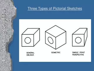
PROJECTIONS OF STRAIGHT LINES. INFORMATION REGARDING A LINE means IT’S LENGTH, POSITION OF IT’S ENDS WITH HP & VP IT’S INCLINATIONS WITH HP & VP WILL BE GIVEN. AIM:- TO DRAW IT’S PROJECTIONS - MEANS FV & TV. SIMPLE CASES OF THE LINE • A VERTICAL LINE ( LINE PERPENDICULAR TO HP & // TO VP) • LINE PARALLEL TO BOTH HP & VP. • LINE INCLINED TO HP & PARALLEL TO VP. • LINE INCLINED TO VP & PARALLEL TO HP. • LINE INCLINED TO BOTH HP & VP.
Orthographic Pattern (Pictorial Presentation) V.P. Note: Fv is a vertical line Showing True Length & Tv is a point. a’ a’ V.P. b’ Fv A V.P. B b’ a’ Y A b’ X Y Y B Tv a b X X H.P. (Pictorial Presentation) V.P. Note: Fv & Tv both are // to xy & both show T. L. Fv a’ b’ b a X Y a b Tv H.P. For Tv 1. FV A Line perpendicular to Hp & // to Vp For Fv a b TV Orthographic Pattern For Tv 2. A Line // to Hp & // to Vp F.V. For Fv T.V.
V.P. Fv inclined to xy Tv parallel to xy. b’ F.V. a’ X Y a b T.V. b’ V.P. a’ V.P. H.P. b’ B F.V. B A Tv inclined to xy Fv parallel to xy. V.P. Y a’ Fv a’ b’ b A a b Ø T.V. X a X Y a Ø Tv b H.P. 3. A Line inclined to Hp and parallel to Vp (Pictorial presentation) Orthographic Projections 4. F.V. A Line inclined to Vp and parallel to Hp (Pictorial presentation) Ø T.V.
V.P. b’ FV a’ On removal of object i.e. Line AB Fv as a image on Vp. Tv as a image on Hp, For Tv For Tv X Y b’ b’ V.P. V.P. a B B F.V. F.V. TV Y Y H.P. a’ a’ b For Fv For Fv A A X X a a b b T.V. T.V. Orthographic Projections Fv is seen on Vp clearly. To see Tv clearly, HP is rotated 900 downwards, Hence it comes below xy. Note These Facts:- Both Fv & Tv are inclined to xy. (No view is parallel to xy) Both Fv & Tv are reduced lengths. (No view shows True Length) 5. A Line inclined to both Hp and Vp (Pictorial presentation)
Projections of Lines: ♣ A line joining any two points along the shortest route is called a straight line. ♣ All problems are first quadrant problems. ♣ Notation: Front view → with dash e.g. a’, a1’ … Top view → without dash e.g. a , a1 … ♣ If a line AB is parallel to a reference plane, then the projection of the line AB obtained on that reference plane will have true length and true inclination. ♣ If a line AB is inclined to a reference plane, then the projection of the line AB obtained on that reference plane will have apparent length.
♣ Vertical line → A line parallel to VP and perpendicular to HP. Horizontal line → A line parallel to HP and perpendicular to VP. ♣ θ = True inclination of the line with the HP Φ = True inclination of the line with the VP θ1 = Apparent inclination of the line with the HP Φ1 = Apparent inclination of the line with the VP ♥ True length makes true inclination ♥ Apparent length makes apparent inclination. ♥ Apparent inclinations are always greater than true inclinations. ♥ Apparent lengths are shorter than the true length.
Line inclined to both the planes: ♣ When the line is inclined to both the planes , both the top view and front view will have reduced length. i.e. Front view length & Top view length → Apparent lengths ♣ Plan → Top view Elevation → Front view
GROUP (A) GENERAL CASES OF THE LINE INCLINED TO BOTH HP & VP ( based on 10 parameters). 1 PROBLEM 1) Line AB is 75 mm long and it is 300 & 400 Inclined to Hp & Vp respectively. End A is 12mm above Hp and 10 mm in front of Vp. Draw projections. Line is in 1st quadrant. b’ b’1 FV TL SOLUTION STEPS: 1) Draw xy line and one projector. 2) Locate a’ 12mm above xy line & a 10mm below xy line. 3) Take 300 angle from a’ & 400 from a and mark TL I.e. 75mm on both lines. Name those points b1’ and b1 respectively. 4) Join both points with a’ and a resp. 5) Draw horizontal lines (Locus) from both points. 6) Draw horizontal component of TL a b1 from point b1 and name it 1. ( the length a-1 gives length of Fv as we have seen already.) 7) Extend it up to locus of a’ and rotating a’ as center locate b’ as shown. Join a’ b’ as Fv. 8) From b’ drop a projector down ward & get point b. Join a & b I.e. Tv. a’ X Y a LFV Ø TV TL b b1
PROBLEM 2: Line AB 75mm long makes 450 inclination with Vp while it’s Fv makes 550. End A is 10 mm above Hp and 15 mm in front of Vp.If line is in 1st quadrant draw it’s projections and find it’s inclination with Hp. b’1 b’ LOCUS OF b1’ Solution Steps:- 1.Draw x-y line. 2.Draw one projector for a’ & a 3.Locate a’ 10mm above x-y & Tv a 15 mm below xy. 4.Draw a line 450 inclined to xy from point a and cut TL 75 mm on it and name that point b1 Draw locus from point b1 5.Take 550 angle from a’ for Fv above xy line. 6.Draw a vertical line from b1 up to locus of a and name it 1. It is horizontal component of TL & is LFV. 7.Continue it to locus of a’ and rotate upward up to the line of Fv and name it b’.This a’ b’ line is Fv. 8. Drop a projector from b’ on locus from point b1 and name intersecting point b. Line a b is Tv of line AB. 9.Draw locus from b’ and from a’ with TL distance cut point b1‘ 10.Join a’ b1’ as TL and measure it’s angle at a’. It will be true angle of line with HP. FV TL 550 a’ y X LFV a 1 450 TV TL LOCUS OF b b b1
PROBLEM 3: Fv of line AB is 500 inclined to xy and measures 55 mm long while it’s Tv is 600 inclined to xy line. If end A is 10 mm above Hp and 15 mm in front of Vp, draw it’s projections,find TL, inclinations of line with Hp & Vp. b’ b’1 FV SOLUTION STEPS: 1.Draw xy line and one projector. 2.Locate a’ 10 mm above xy and a 15 mm below xy line. 3.Draw locus from these points. 4.Draw Fv 500 to xy from a’ and mark b’ Cutting 55mm on it. 5.Similarly draw Tv 600 to xy from a & drawing projector from b’ Locate point b and join a b. 6.Then rotating views as shown, locate True Lengths ab1 & a’b1’ and their angles with Hp and Vp. TL 500 a’ X y a 600 TL b1 b
SOLUTION STEPS: 1.Draw xy line and one projector. 2.Locate a’ 10 mm above xy and a 15 mm below xy line. 3.Draw locus from these points. 4.Cut 60mm distance on locus of a’ & mark 1’ on it as it is LTV. 5.Similarly Similarly cut 50mm on locus of a and mark point 1 as it is LFV. 6.From 1’ draw a vertical line upward and from a’ taking TL ( 75mm ) in compass, mark b’1 point on it. Join a’ b’1 points. 7. Draw locus from b’1 8. With same steps below get b1 point and draw also locus from it. 9. Now rotating one of the components I.e. a-1 locate b’ and join a’ with it to get Fv. 10. Locate tv similarly and measure Angles & PROBLEM 4 :- Line AB is 75 mm long .It’s Fv and Tv measure 50 mm & 60 mm long respectively. End A is 10 mm above Hp and 15 mm in front of Vp. Draw projections of line AB if end B is in first quadrant.Find angle with Hp and Vp. b’ b’1 FV TL LTV 1’ a’ X Y LFV a 1 TV TL b1 b
♣ Procedure to get True length ( from Apparent length ) ♥ The apparent length should be made parallel to reference line XY. ♥ Then draw a vertical projector. ♥ Then use appropriate locus ( case i ) or true length as radius ( case ii ) or the appropriate inclined line ( case iii ) to intersect the above vertical projector to get true length.
♣ Procedure to get Apparent length ( from True length ) ♥ Draw a vertical projector from the true length to get apparent length as a straight line parallel to the reference line XY. ♥ Then draw an arc taking the above apparent length as radius to intersect the appropriate locus ( case i ) or the appropriate inclined line ( case ii ) to get the required apparent length. Note : When a line is inclined to both the reference planes ( H.P. & V.P.) the apparent lengths cannot be a straight line parallel to the reference line XY.
♣ The above procedure used to get true length and apparent length is Rotating line method. ♣ True length : To get true length above reference line XY , use apparent length below reference line XY and vice versa. ♣ Apparent length : To get apparent length above reference line XY , use true length below reference line XY and vice versa. ♣ a & a’ should lie on the same projector. b & b’ should lie on the same projector. m & m’ should lie on the same projector. ♣ While taking the angle Φ or Φ1 , care should be taken to see that a’, a1’, a, a1 … and b’, b1’, b, b1… are grouped separately.
SOLUTION STEPS: 1.Draw xy line and one projector. 2.Locate c’ on xy and c 50mm below xy line. 3.Draw locus from these points. 4.Draw locus of d 15 mm below xy 5.Cut 50mm & 75 mm distances on locus of d from c and mark points d & d1 as these are Tv and line CD lengths resp.& join both with c. 6.From d1 draw a vertical line upward up to xy I.e. up to locus of c’ and draw an arc as shown. 7 Then draw one projector from d to meet this arc in d’ point & join c’ d’ 8. Draw locus of d’ and cut 75 mm on it from c’ as TL 9.Measure Angles & PROBLEM 5 :- T.V. of a 75 mm long Line CD, measures 50 mm. End C is in Hp and 50 mm in front of Vp. End D is 15 mm in front of Vp and it is above Hp. Draw projections of CD and find angles with Hp and Vp. LOCUS OFd’ & d’1 d’ d’1 FV TL c’ Y X LOCUS OFd & d1 d1 d TL TV c
For T.V. VP PP a’ b’ For F.V. a HP b Results:- 1. TV & FV both are vertical, hence arrive on one single projector. 2. It’s Side View shows True Length ( TL) 3. Sum of it’s inclinations with HP & VP equals to 900 ( 4. It’s HT & VT arrive on same projector and can be easily located From Side View. + = 900 ) OBSERVE CAREFULLY ABOVE GIVEN ILLUSTRATION AND 2nd SOLVED PROBLEM. LINE IN A PROFILE PLANE ( MEANS IN A PLANE PERPENDICULAR TO BOTH HP & VP) ORTHOGRAPHIC PATTERN OF LINE IN PROFILE PLANE VT a” a’ A FV LSV b” b’ Y X HT a B TV b
♥ If θ + Φ = 900, then the required projections ( front view and top view ) will lie on a same straight line. ♥ But, if the end P of the line PQ is nearer to VP then the position of the line PQ and the required projections (front view and top view) will be as following:
In these types of problems some situation in the field or some object will be described . It’s relation with Ground ( HP ) And a Wall or some vertical object ( VP ) will be given. Indirectly information regarding Fv & Tv of some line or lines, inclined to both reference Planes will be given and you are supposed to draw it’s projections and further to determine it’s true Length and it’s inclinations with ground. Here various problems along with actual pictures of those situations are given for you to understand those clearly. Now looking for views in given ARROW directions, YOU are supposed to draw projections & find answers, Off course you must visualize the situation properly. CHECK YOUR ANSWERS WITH THE SOLUTIONS GIVEN IN THE END. ALL THE BEST !! APPLICATIONS OF PRINCIPLES OF PROJECTIONS OF LINES IN SOLVING CASES OF DIFFERENT PRACTICAL SITUATIONS.
PROBLEM 14:-Two objects, a flower (A) and an orange (B) are within a rectangular compound wall, whose P & Q are walls meeting at 900. Flower A is 1M & 5.5 M from walls P & Q respectively. Orange B is 4M & 1.5M from walls P & Q respectively. Drawing projection, find distance between them If flower is 1.5 M and orange is 3.5 M above the ground. Consider suitable scale.. TV Wall Q B Wall P A FV
PROBLEM 14:-Two objects, a flower (A) and an orange (B) are within a rectangular compound wall, whose P & Q are walls meeting at 900. Flower A is 1.5M & 1 M from walls P & Q respectively. Orange B is 3.5M & 5.5M from walls P & Q respectively. Drawing projection, find distance between them If flower is 1.5 M and orange is 3.5 M above the ground. Consider suitable scale.. b’ b’1 TL (answer) 3,5M a’ 1.5M x y Wall P B Wall P 1.5M a 3.6M 1M A Wall Q b 5.5M Wall Q F.V.
PROBLEM 15 :- Two mangos on a tree A & B are 1.5 m and 3.00 m above ground and those are 1.2 m & 1.5 m from a 0.3 m thick wall but on opposite sides of it. If the distance measured between them along the ground and parallel to wall is 2.6 m, Then find real distance between them by drawing their projections. TV B 0.3M THICK A FV
PROBLEM 15 :- Two mangos on a tree A & B are 1.5 m and 3.00 m above ground and those are 1.2 m & 1.5 m from a 0.3 m thick wall but on opposite sides of it. If the distance measured between them along the ground and parallel to wall is 2.6 m, Then find real distance between them by drawing their projections. TV B A 3.00 m 0.3M THICK b’ b1’ 1.5m a’ FV 0.3m WALL (GL) X Y b 1.5m Wall thickness 1.2m a REAL DISTANCE BETWEEN MANGOS A & B IS =a’ b1’ 2.6m
PROBLEM 16 :- oa, ob & oc are three lines, 25mm, 45mm and 65mm long respectively.All equally inclined and the shortest is vertical.This fig. is TV of three rods OA, OB and OC whose ends A,B & C are on ground and end O is 100mm above ground. Draw their projections and find length of each along with their angles with ground. TV O 65 mm C 25mm A FV 45 mm B
PROBLEM 16 :- oa, ob & oc are three lines, 25mm, 45mm and 65mm long respectively.All equally inclined and the shortest is vertical.This fig. is TV of three rods OA, OB and OC whose ends A,B & C are on ground and end O is 100mm above ground. Draw their projections and find length of each along with their angles with ground. Tv O o’ C A TL2 100 TL1 Fv TL3 x y b1’ c’ a’ b’ a1’ c1’ B a 25 Answers: TL1 TL2 & TL3 o 45 65 b c
N PROBLEM 17:- A pipe line from point A has a downward gradient 1:5 and it runs due East-South. Another Point B is 12 M from A and due East of A and in same level of A. Pipe line from B runs 200 Due East of South and meets pipe line from A at point C. Draw projections and find length of pipe line from B and it’s inclination with ground. 5 1 Downward Gradient 1:5 A 12 M B E C S
PROBLEM 17:- A pipe line from point A has a downward gradient 1:5 and it runs due South - East. Another Point B is 12 M from A and due East of A and in same level of A. Pipe line from B runs 150 Due East of South and meets pipe line from A at point C. Draw projections and find length of pipe line from B and it’s inclination with ground. 12m 5 b’ 5 a’ 1 1 Downward Gradient 1:5 FV N TL ( answer) A 12 M B E c’ c’1 c’2 x y N W b EAST a 450 C 150 TV S TL ( answer) = a’ c’2 c = Inclination of pipe line BC DUE SOUTH -EAST SOUTH
N S W PROBLEM 18: A person observes two objects, A & B, on the ground, from a tower, 15 M high, At the angles of depression 300 & 450. Object A is is due North-West direction of observer and object B is due West direction. Draw projections of situation and find distance of objects from observer and from tower also. O 300 450 A B
PROBLEM 18: A person observes two objects, A & B, on the ground, from a tower, 15 M high, At the angles of depression 300 & 450. Object A is is due North-West direction of observer and object B is due West direction. Draw projections of situation and find distance of objects from observer and from tower also. o’ 300 450 15M O a’1 a’ b’ 300 450 a N N A W E b o S Answers: Distances of objects from observe o’a’1 & o’b’ From tower oa & ob B W S
PROBLEM 19:-Guy ropes of two poles fixed at 4.5m and 7.5 m above ground, are attached to a corner of a building 15 M high, make 300 and 450 inclinations with ground respectively.The poles are 10 M apart. Determine by drawing their projections,Length of each rope and distance of poles from building. TV C 15 M 300 A 4.5 M 450 B FV 10 M 7.5M
PROBLEM 19:-Guy ropes of two poles fixed at 4.5m and 7.5 m above ground, are attached to a corner of a building 15 M high, make 300 and 450 inclinations with ground respectively.The poles are 10 M apart. Determine by drawing their projections,Length of each rope and distance of poles from building. c’ c1’ c’2 TV C b’ 300 a’ 15M 450 15 M 7.5M 4.5M 300 A 4.5 M 450 12M B a b FV 10 M 7.5M c Answers: Length of Rope BC= b’c’2 Length of Rope AC= a’c’1 Distances of poles from building = ca & cb
4 M 1.2 M 0.7 M PROBLEM 20:- A tank of 4 M height is to be strengthened by four stay rods from each corner by fixing their other ends to the flooring, at a point 1.2 M and 0.7 M from two adjacent walls respectively, as shown. Determine graphically length and angle of each rod with flooring. TV FV
PROBLEM 20:- A tank of 4 M height is to be strengthened by four stay rods from each corner by fixing their other ends to the flooring, at a point 1.2 M and 0.7 M from two adjacent walls respectively, as shown. Determine graphically length and angle of each rod with flooring. FV a’ TV True Length Answers: Length of each rod = a’b’1 Angle with Hp. = A X Y b’1 b’ 4 M a B 1.2 M 0.7 M 0.7 M b FV 1.2 M TV
TV Hook 5 M D A C 2 M 1.5 M FV B PROBLEM 21:- A horizontal wooden platform 2 M long and 1.5 M wide is supported by four chains from it’s corners and chains are attached to a hook 5 M above the center of the platform. Draw projections of the objects and determine length of each chain along with it’s inclination with ground. H
h’ TV TL 5 M Hook Answers: Length of each chain = a’d’1 Angle with Hp. = d’1 5 M x y (GL) a’d’ b’c’ d c 1.5 M D h a b A C 2 M 2 M 1.5 M FV B PROBLEM 21:-A horizontal wooden platform 2 M long and 1.5 M wide is supported by four chains from it’s corners and chains are attached to a hook 5 M above the center of the platform. Draw projections of the objects and determine length of each chain along with it’s inclination with ground. H
Ceiling TV Bulb Side wall Front wall H Switch D L Observer PROBLEM 22. A room is of size 6.5m L ,5m D,3.5m high. An electric bulb hangs 1m below the center of ceiling. A switch is placed in one of the corners of the room, 1.5m above the flooring. Draw the projections an determine real distance between the bulb and switch.
PROBLEM 22. A room is of size 6.5m L ,5m D,3.5m high. An electric bulb hangs 1m below the center of ceiling. A switch is placed in one of the corners of the room, 1.5m above the flooring. Draw the projections an determine real distance between the bulb and switch. 6.5m Ceiling TV b’ 1m b’1 Bulb Side wall 3.5m Front wall a’ H 1.5 Switch x y a D L Observer 5m b B- Bulb A-Switch Answer :- a’ b’1
PROBLEM 23:- A PICTURE FRAME 2 M WIDE AND 1 M TALL IS RESTING ON HORIZONTAL WALL RAILING MAKES 350 INCLINATION WITH WALL. IT IS ATTAACHED TO A HOOK IN THE WALL BY TWO STRINGS. THE HOOK IS 1.5 M ABOVE WALL RAILING. DETERMINE LENGTH OF EACH CHAIN AND TRUE ANGLE BETWEEN THEM TV 350 1.5 M 1 M FV 2 M Wall railing
(chains) (chains) PROBLEM 23:- A PICTURE FRAME 2 M WIDE AND 1 M TALL IS RESTING ON HORIZONTAL WALL RAILING MAKES 350 INCLINATION WITH WALL. IT IS ATTAACHED TO A HOOK IN THE WALL BY TWO STRINGS. THE HOOK IS 1.5 M ABOVE WALL RAILING. DETERMINE LENGTH OF EACH CHAIN AND TRUE ANGLE BETWEEN THEM h’ TV a’b’ 1.5M 350 A 1.5 M B 1M 1 M c’d’ D (wall railing) FV X Y ad a1 2 M C Wall railing (frame) h Answers: Length of each chain= hb1 True angle between chains = b1 bc