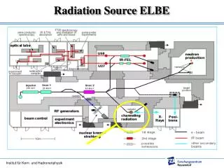
Radiation Source
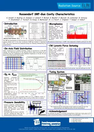
half Cell. 3 TESLA cell. 2 HOM coupler. cathode. e - -beam. TESLA cell tuner. sc choke filter (to prevent RF leakage). FZD coupler & pickup ant. ½ cell tuner. main coupler. electrical field distribution along cavity axis for E z,max =50MV/m. 63.1%. 96.6%. 100%. 97.0%.

Radiation Source
E N D
Presentation Transcript
half Cell 3 TESLA cell 2 HOM coupler cathode e--beam TESLA cell tuner sc choke filter (to prevent RF leakage) FZD coupler & pickup ant. ½ cell tuner main coupler electrical field distribution along cavity axis for Ez,max=50MV/m 63.1% 96.6% 100% 97.0% stepping motor & gearbox tuning lever 3-cell cavity tuning spindle tuning lever 1/2-cell cavity Acknowledgement We acknowledge the support of the European Community-Research Infrastructure Activity under the FP6 “Structuring the European Research Area” programme (CARE, contract number RII3-CT-2003-506395) and the support of the German Federal Ministry of Education and Research grant 05 ES4BR1/8. Radiation Source Rossendorf SRF-Gun Cavity Characteristics A. Arnold1, H. Buettig1, D. Janssen1, U. Lehnert1, P. Michel1, K. Moeller1, P. Murcek1, Ch. Schneider1, R. Schurig1, F. Staufenbiel1, J. Teichert1, R. Xiang1, A. Matheisen2, B. v. d. Horst2, J. Stephan3, T. Kamps4, V. Volkov5 Introduction Microphonics damped membrane pumps • detuning measured by demodulated LL phase controller signal • FFT using one minute time signals show discrete PSD (power spectral density) • strong damping of the membrane pumps and its vacuum tubes was needed to achieve stable cavity operation Helium refrigerator desired field flatness: [0.6 - 1 – 1 – 1] The SRF-Gun development at FZD has made lot of progress. The installation of the injector module next to the linear accelerator ELBE was finished in September 2007. The cavity characteristics measured during the following commissioning are presented here. Microphonics (closed loop σ = 0.055° rms) comparable to ELBE & sufficient for CW CW Lorentz Force Detuning • 1st V-Test (cleaning done @ DESY): • - Residual surface resistance Rres=3.4nΩ • - Strong field emission, two Q-switches • (thermal breakdown @ activated FE) • Supposed problem: surface pollution out of the choke (cleaning not feasible with lance) • 2nd V-Test (cleaning done @ DESY): • - Choke rinsing by special HPR lance • - HPR lance crashed with cavity during • choke cleaning → worst result / limit FE • 3rd V-Test (cleaning done @ ACCEL): • - Caused by high risk no choke rinsing • - No problems occurred but only 20MV/m • 4th V-Test (cleaning done @ ACCEL): • - Choke rinsing by special HPR lance • - Achieved Epeak better but also limit FE • - To estimate position of FE all 4 • passband modes measured On-Axis Field Distribution • the electric & magnetic surface field causes a Lorentz Force pressure on the cavity wall • the induced neg. frequency shift is proportional to the square of gradient Under consideration of cooldown shrinking, change of permittivity & final BCP cleaning, the field distribution of the operated cavity inside the module can be calculated using the fundamental mode passband frequencies at 2K and the last known cavity state before final cleaning. Detuning 3-times higher than TESLA 9-cell cavities – but still sufficient for CW Tuning System • Tektronix RSA3408A • Rep Rate: 2kHz & 125kHz • Beam current: 230nA • Bunchcharge: 115pC @ 2kHz and 1.8pC @ 125kHz • Gradient: 5MV/m (ca. 2MeV) Q0 vs. Epeak Monopole HOM • R/Q calculation from measured channel power for the marked monopole HOMs results in: • maximum achievable field only 1/3 of the designed value of Epeak=50MV/m • measured Q0 is 10 times lower than in all vertical tests • no Q degradation found during the 1st year of operation • first eight Q vs. E measurements limited by FE & He consumption HOM @ 2.491GHz R/Q = 18.90 Ω → HOM Power @ 1mA = 2.0 W HOM @ 2.822GHz R/Q = 1.87 Ω → HOM Power @ 1mA = 4.7 W • Due to the low rep rates down to some ten kHz and the unknown HOM spectra of a new welded cavity, at least one HOM coupler should be preferred • In the case of two different tuners a shifting of the HOM spectra with one of them seems possible while the fundamental mode is kept constant using the other one! • 9th test after high power processing (HPP) up to Epeak=25MV/m results in stable CW operation up to 17.6MV/m, above this level cavity starts to quench Pressure Sensibility • pressure sensibility (230Hz/mBar) is seven times higher than known from ELBE modules which is probably caused by different cavity design (weak half cell) • no problem seen for the LL controller and max. available RF Power due to helium pressure stability of 0.1mbar • No problems during 2K cooldown • Frequency shift same as expected from TESLA cells • But 380kHz to high because change of ∆εr not considered The resolution and the tuning span of both tuners are sufficient but the hysteresis has to be improved within the next maintenance! • FZ Dresden Rossendorf, Dresden, Germany • DESY, Hamburg, Germany • IKS, Dresden, Germany • BESSY, Berlin, Germany • Budker Institute of Nuclear Physics, Novosibirsk, Russia Member of the Leibniz Association Bautzner Landstr. 128 01328 Dresden/Germany http://www.fzd.de Contact: André Arnold Institute of Radiation Physics, Radiation Source ELBE Email: a.arnold@fzd.de Phone: +49 351 260 - 3382