Low emittance tuning in light sources
280 likes | 454 Views
Low emittance tuning in light sources. R. Bartolini Diamond Light Source Ltd and John Adams Institute, University of Oxford. Jesus College, Oxford 18 th May 2011. Introduction to 3 rd generation light sources Low emittance lattices Beam optics studies linear optics

Low emittance tuning in light sources
E N D
Presentation Transcript
Low emittance tuning in light sources R. Bartolini Diamond Light Source Ltd and John Adams Institute, University of Oxford Jesus College, Oxford 18th May 2011
Introduction to 3rd generation light sources • Low emittance lattices • Beam optics studies • linear optics • nonlinear optics • Further techniques for low emittance control • optics and coupling control with spectral lines analysis • dispersion and couplign free steering Outline Jesus College, Oxford 18th May 2011
ESRF SSRF 3rd generation storage ring light sources 1992ESRF, France (EU) 6 GeV ALS, US 1.5-1.9 GeV 1993 TLS, Taiwan 1.5 GeV 1994ELETTRA, Italy 2.4 GeV PLS, Korea 2 GeV MAX II, Sweden 1.5 GeV 1996APS, US 7 GeV LNLS, Brazil 1.35 GeV 1997 Spring-8, Japan 8 GeV 1998BESSY II, Germany 1.9 GeV 2000ANKA, Germany 2.5 GeV SLS, Switzerland 2.4 GeV 2004SPEAR3, US 3 GeV CLS, Canada 2.9 GeV 2006: SOLEIL, France 2.8 GeV DIAMOND, UK 3 GeV ASP, Australia 3 GeV MAX III, Sweden 700 MeV Indus-II, India 2.5 GeV 2008SSRF, China3.4 GeV 2009PETRA-III, D 6 GeV 2011ALBA, E 3 GeV
3rd generation storage ring light sources under construction or planned NLSL-II > 2011NSLS-II, US 3 GeV SESAME, Jordan 2.5 GeV MAX-IV, Sweden 1.5-3 GeV TPS, Taiwan3 GeV CANDLE, Armenia 3 GeV Max-IV Jesus College, Oxford 18th May 2011
Brilliance and low emittance The brilliance of the photon beam is determined (mostly) by the electron beam emittance that defines the source size and divergence
Low emittance lattices Lattice design has to provide low emittanceandadequate space in straight sections to accommodate long Insertion Devices Minimise and D and be close to a waist in the dipole Zero dispersion in the straight section was used especially in early machines avoid increasing the beam size due to energy spread hide energy fluctuation to the users allow straight section with zero dispersion to place RF and injection decouple chromatic and harmonic sextupoles DBA and TBA lattices provide low emittance with large ratio between Flexibility for optic control for apertures (injection and lifetime)
APS ALS DBA and TBA Double Bend Achromat (DBA) Triple Bend Achromat (TBA) DBA used at: ESRF, ELETTRA, APS, SPring8, Bessy-II, Diamond, SOLEIL, SPEAR3 ... TBA used at ALS, SLS, PLS, TLS …
Breaking the achromatic condition Leaking dispersion in straight sections reduces the emittance ESRF 7 nm 3.8 nm APS 7.5 nm 2.5 nm SPring8 4.8 nm 3.0 nm SPEAR3 18.0 nm 9.8 nm ALS (SB) 10.5 nm 6.7 nm APS The emittance is reduced but the dispersion in the straight section increases the beam size ASP Need to make sure the effective emittance and ID effects are not made worse
Low emittance lattices MAX-IV New designs envisaged to achieve sub-nm emittance involve Damping Wigglers Petra-III: 1 nm NSLS-II: 0.5 nm MBA MAX-IV (7-BA): 0.5 nm Spring-8 (10-BA):160 pm 10-DBA abandoned because no DA, reverted to a QBA Spring-8 upgrade
Oxford 15 miles Diamond aerial view Frascati 1200 miles Diamond is a third generation light source open for users since January 2007 100 MeV LINAC; 3 GeV Booster; 3 GeV storage ring 2.7 nm emittance – 300 mA – 18 beamlines in operation (10 in-vacuum small gap IDs)
Energy 3 GeV Circumference 561.6 m No. cells 24 Symmetry 6 Straight sections 6 x 8m, 18 x 5m Insertion devices 4 x 8m, 18 x 5m Beam current 300 mA (500 mA) Emittance (h, v) 2.7, 0.03 nm rad Lifetime > 10 h Min. ID gap7 mm (5 mm) Beam size (h, v)123, 6.4 mm Beam divergence (h, v)24, 4.2 mrad (at centre of 5 m ID) Beam size (h, v)178, 12.6 mm Beam divergence (h, v)16, 2.2 mrad (at centre of 8 m ID) Diamond storage ring main parametersnon-zero dispersion lattice 48 Dipoles; 240 Quadrupoles; 168 Sextupoles (+ H and V orbit correctors + 96 Skew Quadrupoles) 3 SC RF cavities; 168 BPMs Quads + Sexts have independent power supplies
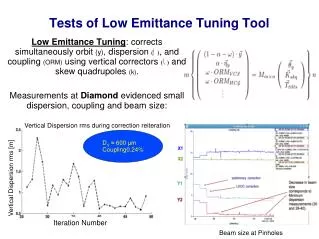
Hor. - beating Ver. - beating Quadrupole gradient variation Linear optics modelling with LOCOLinear Optics from Closed Orbit response matrix – J. Safranek et al. Modified version of LOCO with constraints on gradient variations (see ICFA Newsl, Dec’07) - beating reduced to 0.4% rms Quadrupole variation reduced to 2% Results compatible with mag. meas. and calibrations LOCO allowed remarkable progress with the correct implementation of the linear optics
Skew quadrupoles can be simultaneously zero the off diagonal blocks of the measured response matrix and the vertical disperison Linear coupling correction with LOCO (II)
BPMs coupling LOCO fits also the BPM gain and coupling BPM coupling includes mechanical rotation and electronics cross talk These data are well reproducible over months Jesus College, Oxford 18th May 2011
Residual vertical dispersion Without skew quadrupoles off r.m.s. Dy = 14 mm After LOCO correction r.m.s. Dy = 700 μm (2.2 mm if BPM coupling is not corrected) Jesus College, Oxford 18th May 2011
Measured emittances Coupling without skew quadrupoles off K = 0.9% (at the pinhole location; numerical simulation gave an average emittance coupling 1.5% ± 1.0 %) Emittance [2.78 - 2.74] (2.75) nm Energy spread [1.1e-3 - 1.0-e3] (1.0e-3) After coupling correction with LOCO (2*3 iterations) 1st correction K = 0.15% 2nd correction K = 0.08% V beam size at source point 6 μm Emittance coupling 0.08% → V emittance 2.2 pm Variation of less than 20% over different measurements
Comparison machine/model andLowest vertical emittance * best achieved
Non-linear optics optimisation and control with low emittance lattices Low emittance Large Nat. Chromaticity with Strong quads and Small Dispersion Strong SX Small Apertures (Dynamic and Momentum apertures) Usually the phase advance per cell is such that low resonance driving terms are automatically compensated (to first order) Numerical optimisation is however unavoidable need 6D tracking (watch out alpha_2) use DA and FM plots use MOGA ! MOGA in elegant to optimise 8 sextupole families at Diamond improved the Touschek lifetime by 20 % Jesus College, Oxford 18th May 2011
Frequency map and detuning with momentum comparison machine vs model (I) detuning with momentum model and measured FM measured FM model Sextupole strengths variation less than 3% The most complete description of the nonlinear model is mandatory ! Measured multipolar errors to dipoles, quadrupoles and sextupoles (up to b10/a9) Correct magnetic lengths of magnetic elements Fringe fields to dipoles and quadrupoles Substantial progress after correcting the frequency response of the Libera BPMs
Frequency map and detuning with momentum comparison machine vs model (II) Synchrotron tune vs RF frequency DA measured DA model The fit procedure based on the reconstruction of the measured FM and detunng with momentum describes well the dynamic aperture, the resonances excited and the dependence of the synchrotron tune vs RF frequency R. Bartolini et al. Phys. Rev. ST Accel. Beams 14, 054003 Jesus College, Oxford 18th May 2011
Example: SpectralLinesfortracking data for the Diamond lattice Spectral Lines detected with SUSSIX (NAFF algorithm) Frequency Analysis of betatron motion • e.g. in the horizontal plane: • (1, 0) 1.10 10–3horizontal tune • (0, 2) 1.04 10–6 Qx + 2 Qz • (–3, 0) 2.21 10–7 4 Qx • (–1, 2) 1.31 10–7 2 Qx + 2 Qz • (–2, 0) 9.90 10–8 3 Qx • (–1, 4) 2.08 10–8 2 Qx + 4 Qz Each spectral line can be associated to a resonance driving term J. Bengtsson (1988): CERN 88–04, (1988). R. Bartolini, F. Schmidt (1998), Part. Acc., 59, 93, (1998). R. Tomas, PhD Thesis (2003)
Nonlinear dynamics from betatron oscillations All BPMs have turn-by-turn capabilities • excite the beam diagonally • measure tbt data at all BPMs • colour plots of the FFT H BPM number QX = 0.22 H tune in H Qy = 0.36 V tune in V V All the other important lines are linear combination of the tunes Qx and Qy BPM number m Qx + n Qy frequency / revolution frequency See also R. Bartolini et al. Phys. Rev. ST Accel. Beams 11, 104002 (2008)
Frequency Maps and amplitudes and phases of the spectral line of the betatron motion can be used to compare and correct the real accelerator with the model LOCO Closed Orbit Response Matrix from model ongoing work fitting quadrupoles, etc Linear lattice correction/calibration Closed Orbit Response Matrix measured Nonlinear calibration and correction Spectral lines + FMA from model fitting sextupoles and higher order multipoles Nonlinear lattice correction/calibration Spectral Lines + FMA measured Combining the complementary information from FM and spectral line should allow the calibration of the nonlinear model and a full control of the nonlinear resonances
Further techniques A. Franchi et al., PRSTAB 14, 034002 (2011) Jesus College, Oxford 18th May 2011
ESRF coupling correction with spectral lines (I) Jesus College, Oxford 18th May 2011 Courtesy A. Franchi
ESRF coupling correction with spectral lines (II) Jesus College, Oxford 18th May 2011 Courtesy A. Franchi
Last year results on low emittance tuning and the achievement of a vertical emittance of 2.2 pm have sparked quite some interest from the Damping ring community (CLIC and ILC) and from the Super B In collaboration with the SuperB team (P. Raimondi,. M. Biagini, S: Liuzzo) Diamond has been used as a test-bed for new techniques for low emittance tuning based on dispersion free steering and coupling free steering. Low emittance tuning at Diamond for SuperB 4 MD shifts at DLS November - February New JAI PhD student to start in October
Conclusions Third generation light sources provide a very reliable source of high brightness, very stable X-rays The agreement with model is excellent for the linear optics and improvements can be foreseen for the nonlinear optics At Diamond several very different optics have all been succesfully operated with residual beta beating of 1% or less, with excellent coupling control. Careful alignment and independent power supplies in all quadrupoles and sextupoles have allowed a very good control of the linear and nonlinear optics Diamond is an ideal test-bed for testing low emittacne tuning techniques relevant for SuperB Anyone interested is most welcome to join these studies. Thank you for your attention ! Jesus College, Oxford 18th May 2011