Download
1 / 22
230 likes | 371 Views
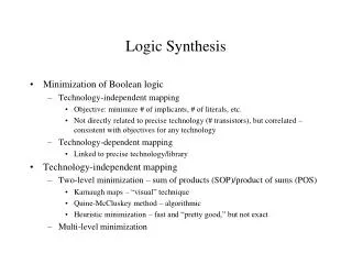
Logic synthesis is the process of translating higher-level descriptions into lower-level representations, particularly in the context of hardware design. It involves the combination of components to produce a functional system, often contrasted with analysis. Effective RTL (Register Transfer Level) coding is crucial for synthesis, including rules like avoiding internally generated clocks and keeping design technology-independent. This guide outlines essential practices for achieving optimal design, such as using clear documentation, appropriate coding structure, and separate logic/clock handling.

E N D
assign z=a&b a z b Logic Synthesis
What is Synthesis • synthesis • /sinth siss/ • noun (pl.syntheses /sinth seez/) 1 the combination of components to form a connected whole. Often contrasted with ANALYSIS. 2 the production of chemical compounds by reaction from simpler materials. • — DERIVATIVES synthesistnoun. • — ORIGIN Greek sunthesis, from suntithemai‘place together’.
Synthesis • Translation from a higher-level description to a lower-level description • Logic or RTL synthesis: Translation of RTL code to logic gates and other basic components
Guideline • Avoid internally generated clocks • Instead, use a separate block for clock generation
Rule • Avoid combinational feedback
Do not use if statements to describe larger than 2-to-1 MUXs if (sel == 0) o = a; else if (sel == 1) o = b; else if (sel == 2) then o <= c; else o <= d;
Use Case statement instead case sel 0: o = a; 1: o = b; 2: o = c; 3: o = d; endcase
Register all outputs • Bad • Better • Ideal
Avoid glue logic at the top • Incorrect • Correct
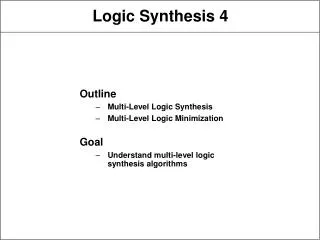
RTL coding for synthesis • Keep code technology independent (no instantiations of technology primitives) • Clock gating logic and reset generation kept in one block • Avoid multiple clocks per block (Sync logic should be in a separate module) • No glue logic at the top • Register all outputs
RTL coding for logic • No incomplete sensitivity lists • Use the case statement for muxes, specifying the “others” case
RTL coding for state machines • Use enumerated types, do not perform state assignment • Separate combinational logic from state registers • Use case statements
Specifying design constraints • Timing (clock frequency, I/O timing) • Area (mm^2, #CLBs) • I/O pads and pins
Design for Use vs Design for Reuse • Design for use • Good documentation • Good code • Thorough commenting • Well-designed verification environment • Robust scripts • Design for reuse (3x design for use effort) • Design to solve a general problem • Support for multiple technologies • Multiple simulator support (both VHDL and Verilog) • Support for standard-based interfaces • Verified to a high level of confidence • Fully documented
RTL coding guidelines for reuse • Include a header mentioning • Filename • Author • Date • Time • Abstract • Modification history • Use comments extensively, but not pointlessly • Use indentation (recommended 2 spaces per nest)
Header example // File : tsu.v // Author : K. Tatas // Date : 09/06/07 // Version : 0.1 // Abstract : TSU top-level structural file // Modification History: // Date By Version Change Description // 9/06/07K. Tatas 0.1 Original // 11/07/07K.Tatas 1.1. Included Interrupt block // 03/08/07 K. Tatas 1.2 changes from OPB to PLB bus
I/O ordering • One signal per line • Separate inputs from outputs • Order • Clocks • Resets • Control signals • Data/address signals module ack_queue (thread_out, status_out, aq_wr_en, clk, rst_n, aq_wr_en, aq_rd_en,aq_in, addr_aq_wr, addr_aq_rd); input clk //Clock signal (System clock) input rst_n //Reset signal (System reset) //////////////////////////////Control signals------------------------------------------- input [aq_fields-1:0] aq_wr_en //Write Enable signal (from control logic) input aq_rd_en //Read Enable signal (from control logic) //////////////////////////////DATA/ADDRESS signals---------------------------------------------- input [wordlength-1:0]aq_in //AQ number output [wordlength-1:0] thread_out //thread number output [wordlength-1:0]status_out //status input [log(aq_depth)-1: 0] addr_aq_wr//ack queue write address input [log(aq_depth)-1: 0] addr_aq_rd //ack queue read address
RTL coding guidelines for reuse • Use std_logic types • Do not use hard-coded numeric values • Use packages • Use descriptive names for signals, enitities, etc. • Use nominal, not positional association in port mapping of components • Use suffixes for signal names • _n for active low signals such as reset • _r for signals that are outputs of registers • _p, _p1, _p2, for phases of the same signal
Guideline • Avoid mixed clock edges • If not possible, isolate mixed clock domains