Download
1 / 22
220 likes | 288 Views
Hierarchical Cooperation Achieves Linear Scaling in Ad Hoc Wireless Networks. David Tse Wireless Foundations U.C. Berkeley MIT LIDS May 7, 2007 Joint work with Ayfer Ozgur and Olivier Leveque at EPFL. TexPoint fonts used in EMF: A A A A A A A A A A. Scaling of Ad Hoc Wireless Networks.

E N D
Hierarchical Cooperation Achieves Linear Scaling in Ad Hoc Wireless Networks David Tse Wireless Foundations U.C. Berkeley MIT LIDS May 7, 2007 Joint work with Ayfer Ozgur and Olivier Leveque at EPFL TexPoint fonts used in EMF: AAAAAAAAAA
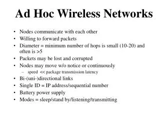
Scaling of Ad Hoc Wireless Networks • 2n nodes randomly located in a fixed area. • n randomly assigned source-destination pairs. • Each S-D pair demands the same data rate. • How does the total throughput T(n) of the network scale with n?
How much can cooperation help? Courtesy: David Reed of MIT ? Gupta-Kumar 00
Main Result Linear capacity scaling is achievable with intelligent cooperation. More precisely: For every > 0, we construct a cooperative scheme that can achieve a total throughput T(n) = n1-.
Channel Model • Baseband channel gain between node k and l: where rkl is the distance apart and kl is the random phase (iid across nodes). • is the path loss exponent (in power)
Dense networks • Setting: many nodes all within communication range of each other. • Number of nodes are large but nearest nodes are still far field from each other. • Example: • Berkeley campus (1 square km) • n = 10,000 users (n >> 1) • Typical distance between nearest neighbors: 10m • Carrier frequency: 2.4 GHz => wavelength ~0.1m • Will talk about extended networks later.
Gupta-Kumar Capacity is Interference-Limited • Long-range transmission causes too much interference. • Nearest-neighbor transmission means each packet is transmitted times (multi-hop). • To get linear scaling, must be able to do many simultaneous long-range transmissions. • How to deal with interference? • A natural idea: distributed MIMO (Aeron & Saligrama 06).
MIMO:Multiple Transmit Multiple Receive Antennas • The random MxM channel matrix allows transmission of M parallel streams of data. • Originally conceived for antennas co-located at the same device.
Distributed MIMO • MIMO effect can be simulated if nodes within each cluster can cooperate. • But cooperation overhead limits performance. • What kind of architecture minimizes overhead?
A 3-Phase Scheme • Divide the network into clusters of size M nodes. • Focus first on a specific S-D pair. source s wants to send M bits to destination d. Phase 1 : Setting up Tx cooperation: 1 bit to each node in Tx cluster Phase 2: Long-range MIMO between s and d clusters. Phase 3: Each node in Rx cluster quantizes signal into k bits and sends to destination d.
Parallelization across S-D Pairs Phase 1: Clusters work in parallel. Sources in each cluster take turn distributing their bits. Total time = M2 Phase 2: 1 MIMO trans. at a time. Total time = n Phase 3: Clusters work in parallel. Destinations in each cluster take turn collecting their bits. Total time = kM2
Back-of-the-Envelope Throughput Calculation total number of bits transferred = nM total time in all three phases = M2 +n + kM2 throughput: bits/second Optimal cluster size Best throughput:
Further Parallelization • In phase 1 and 3, M2 bits have to be exchanged within each cluster, 1 bit per node pair. • Previous scheme exchanges these bits one at a time (TDMA), takes time M2. • Can we increase the spatial reuse ? • Can break the problem into M sessions, each session involving M S-D pairs communicating 1 bit with each other: cooperation = communication • Any better scheme for the small network can build a better scheme for the original network.
Recursion Lemma: A scheme with thruput Mb for the smaller network yields for the original network a thruput: with optimal cluster size:
MIMO + Hierarchical Cooperation-> Linear Scaling . Long-range MIMO Setting up Tx cooperation Cooperate to decode At the highest level hierarchy, cluster size is of the order n1- => near network-wide MIMO cooperation.
Upper Bound • A simple upper bound: each source node has the benefit of all other nodes in the network cooperating to receive without interference from other nodes. • Each source gets a rate of at most order log n. • Yields an upper bound on network throughput • The hierarchical scheme is nearly information theoretically optimal.
Transmit Power Requirement of Scheme • At all levels of hierarchy, transmit powers in the MIMO phase can be set such that the total average received SNR at each node is 0 dB. • This yields MIMO rate linear with the cluster size in phase 2. • This also explains why a fixed number of quantization bits per sample suffices. • At the total level of hierarchy, the transmit power per node is P/n. • We have power to spare!
From Dense to Extended Networks • So far we have looked at dense networks, where the total area is fixed. • Another natural scaling is to keep the density of nodes fixed and the networks covers an increasing area. • Distances are increased by a factor of n1/2 in extended networks. • Equivalently, an extended network is a dense network with power constraint P/n/2 per node. • Immediate result: For =2, linear scaling can be achieved for extended networks.
Extended Networks: >2 • For > 2, even when each node transmits at full power in the MIMO phase, total received SNR per node = n1-/2 -> 0 • n by n MIMO transmission is now power-limited: CMIMO ~ total Rx power = n2-/2 • Can the hierarchical scheme achieve arbitrarily close to this scaling?
Quantization is a Problem • Subtle issue: information per received sample per Rx antenna in MIMO goes to zero. • If we use fixed number of bits to quantize each sample, we are doomed. • Cannot use vanishing number of bits either. • Use bursty transmission so that during transmission the SNR at each Rx antenna is again 0db. • We are still power-efficient but Rx cooperation is no longer onerous. • We are operating at the boundary of power-limited and degrees-of-freedom-limited regimes.
Is Our Scheme Optimal for Extended Networks? We show: for all , the cutset bound scales like the total received power under no Tx cooperation. A dichotomy: > 3: this total power is , dominated by transfer between the few boundary users. Multihop is optimal. <3: total power is n2-/2, dominated by transfer between the many interior users . Our scheme is optimal. Achievable (Top Level of Hierarchical Scheme) Cutset Bound Rx cluster: size n1- Distance Tx cluster: size n1-
Conclusion • Hierachical cooperation allows network-wide MIMO without significant cooperation overhead. • Network wide MIMO achieves a linear number of degrees of freedom. • This yields a linear scaling law for dense networks. • It also achieves maximum energy transfer in extended networks when path loss exponent is less than 3. • Better than Gupta-Kumar scaling is possible in the low attenuation regime.