Development Concepts for 20T Dipole Magnets: Innovations in High Energy Physics
200 likes | 341 Views
To advance our understanding of fundamental physics, we propose the design and development of new 20T dipole magnets that allow exploration of higher energies. This project emphasizes the importance of early planning and incorporates emerging technologies like High-Temperature Superconductors (HTS). Through a careful comparison of various design configurations and the establishment of uniform criteria, we aim to assess feasibility, performance, and force impacts. Our ongoing work involves optimizing coil designs and evaluating active shielding strategies to enhance compactness and efficiency.

Development Concepts for 20T Dipole Magnets: Innovations in High Energy Physics
E N D
Presentation Transcript
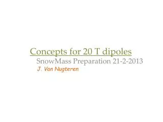
Concepts for 20 T dipoles SnowMass Preparation 21-2-2013 J. Van Nugteren
We want a new 20T Dipole • Higher energies to find new fundamental physics • So we can improve our understanding of the universe we live in • However development of such a magnet will take some time • Therefore we need to start thinking now • Many ideas ‘floating’ around • Many new technologies such as HTS • Assignment: make first steps within context EUCARD I/II (Wallpapers NASA)
Development Plan • Started November 2012 in the framework of PhD • Work far from complete • Compare all (or most relevant) designs/layouts • Boundaries • Iron influence • With – gain 2 T for single aperture • Without – B distribution modified • Active shielding? • Conductor • Existing performance • Future extrapolated performance -> to prospect ultimate possibilities • Field quality • Not too much focus on field quality yet. Because winding pack is thick, it can be corrected for later.
Making a Fair Comparison • All designs/layouts must follow same set of rules • 20 T operating field • same critical surfaces for conductor • same operating points (80%Ic) • same operating temperature (1.9 K) • same free bore (40 mm) • same assumptions on how to deal with forces • same shielding/iron • Compare in terms of • Forces and stresses in coil • Amount of conductor • Feasibility • Need to watch out to compare also to some designs of different groups.
Design Options • Configuration per Layer • Cos-Theta • Block • Canted Cos-Theta • Perhaps other Full Cos-Theta Full Block Canted Cosine Theta (CCT)
Design Options • Conductor per Layer • NbTi • Nb3Sn • YBCO (fieldangle) • BSCCO (stresses) • Cables • Rutherford • Roebel • Cork • Other? • One or multiple power supplies? Miyoshi Measurement Data 1o Godeke Scaling Relation 5o Jc [A/mm2] 10o Bottura Scaling relation McIntyre 20o |B| [T]
Pocket Sized Coil Optimizer New iterative 2D magnet optimization tool Breq yes no J J J J J J Convergence Reached (: Post processing α4 α3 α2 α1 Load input coils Start Breq
Pocket Sized Coil Optimizer Provides playground to create many coil designs (following the rules) for comparison At present we have studied YBCO insert, single aperture only to test the code Ultimate goal is to create comparative tables with many design options for dual aperture Already provided us with some ideas …
Idea 1 – Angle optimization for YBCO The critical current of YBCO tapes/cables is highly dependent on the incident angle of the magnetic field Effect becomes stronger at higher fields Because of this for presently available YBCO, only designs with good field angle inside the insert turn out to be feasible 2 T 20 T
Idea 1 – angular optimization For example - Normal Block Coil
Idea 1 – angular optimization Insert: Crystalized Block Coil //ShardedBlock Coil How to make the ends? (Need 3D model)
Idea 2 - Active Shielding • 20 T magnet would require massive iron yoke • Therefore it was decided to look also at active shield coils • Less weight • More compact • However • Instead of gaining field you lose field • There is something called Blooming Field Effect
Idea 2 - Active Shielding Single aperture – no shield R=16 m 50 Gauss 5 Gauss Note that for the dual aperture case, the result is different (this is an exercise)
Idea 2 - Active Shielding Single aperture – 1 shield block R=1.5 m 50 Gauss 5 Gauss • Requires approximately 10-15% extra conductor
Idea 2 - Active Shielding Single aperture – 2 shield blocks R=0.9m 50 Gauss 5 Gauss
Idea 2 – Dual aperture active shield? Dual aperture gives quadrupole stray field Artistic impression of possible shield layout Yet to be researched + + \ \ \ - - - - + + - - + +
Yet to be done Two-in-One aperture (and its shielding) Iron including saturation Coil ends in 3D models Designs with BSCCO Mechanics Quench Behaviour
PSCO – Simply Nesting Layers • Types of layers • Sector (cosine theta, helical, …) • Block (block coil) • Nesting conditions (in/out) • wallin • wallout • radiusin • radiusout • radiuscen • beampipe • beampipe_sqe • beampipe_sqo • moving