Download
1 / 21
220 likes | 555 Views
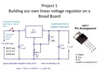
Project 1 Building our own linear voltage regulator on a Bread Board. I recommend adding a switch here. I did on mine. I used two mini or alligator clips here. I used the 9V clip here. 330. We’ll use 12 or 9 V batteries. Project 1 Parts list. 330 ohm resistor

E N D
Project 1Building our own linear voltage regulator on a Bread Board I recommend adding a switch here. I did on mine. I used two mini or alligator clips here I used the 9V clip here 330 We’ll use 12 or 9 V batteries
Project 1 Parts list • 330 ohm resistor • 5K potentiometer (I used a linear 10K Pot worked okay too witch makes it easy to change the voltage) • 0.1 uf capacitor (number on part could be 104) • 10 uf capacitor • LM317 voltage regulator • Suggested parts • 9 Volt clip, and power clips Power in • 2 Mini clips or alligator clips Power out • SPST switch • Exercise - Everyone get your paper and pencil and figure out what are the color code bands are for the resistor above. We’ll then share the answers
Project 2 Logic Probe Bread Board 470 (if 9V battery used) Why? Beginner group project PN2222a C The probes for the circuit are in blue. The ground connection below is left off many schematics assuming that everyone knows that the circuit must have a common ground. Why? B E E B C Long pin The datasheet has the pin-out and many other important pieces of information on our part. Flat side I made a probe out of a popsicle stick, heat sink tubing And some solid core and stranded wire Stranded for flexibility Solid core for tip
1 100K Resistor 1 220 Resistor 2 2N2222 transistors 1 LED Exercise: Everyone figure out what are the colors for the resistor above. We’ll then share the answers Now get the needed parts, note I have put some parts that may look like the correct one, but aren’t. Project 2 part list beginners
Project 2 AdvancedLogic Probe Bread Board 3v to 15V I used 9 V I made a probe out of a popsicle stick, heat sink tubing And some solid core and stranded wire Solid core for tip Advanced groups project Stranded for flexibility
Project 2 Advanced Logic probe Parts List • CD4001 (and 14 pin socket nice I don’t have a supply) • RED LED • GREEN LED • YELLOW LED • 9 Volt clip, and probes (made) • 2.2M • 6.8M • 2x1.8K • 1.5K • 2x100nf (104 or 0.1 uF) For both Beginner and Advanced projects We need to supply power to our board, we can use alligator clips or micro clips and connect to the board under test and use its power, or we can have our own like a 9 V battery. You decide what yours needs. Test clips, we need to connect to the circuit that we are testing. Usually the ground is a alligator or micro clip so we don’t have to hold it. But the test probe wants to be a point or clip to touch or hold on to and make the reading. We can make our own clips from some of the parts I have brought or use wire and a stick handle for us to hold onto.
Project 2 Logic probe with the software and the Arduino /* Button Turns on and off a light emitting diode(LED) connected to digital pin 8, when pressing a pushbutton attached to pin 2. The circuit: * LED attached from pin 8 to ground * pushbutton attached to pin 2 from +5V * 10K resistor attached to pin 2 from ground */ // constants won't change. They're used here to set pin numbers: const int buttonPin = 2; // the number of the pushbutton pin const int ledPin = 8; // the number of the LED pin // variables will change: int buttonState = 0; // variable for reading the pushbutton status
void setup() { // initialize the LED pin as an output: pinMode(ledPin, OUTPUT); // initialize the pushbutton pin as an input: pinMode(buttonPin, INPUT); } void loop(){ // read the state of the pushbutton value: buttonState = digitalRead(buttonPin); // check if the pushbutton is pressed. // if it is, the buttonState is HIGH: if (buttonState == HIGH) { // turn LED on: digitalWrite(ledPin, HIGH); } else { // turn LED off: digitalWrite(ledPin, LOW); }}
Project 2 -Analog Voltage with using aDVM and Arduino 4.7K DVM
Project 3 -Build an Oscillator (pulse generator) using a 555 IC Bread board I used one mini clip connected to pin 3 as the output and common ground as the output lines My power was the 9 V battery and clip For testing only
Project 3 Part list • NE555 • 1K • 100K potentiometer use trim pot so it is easy to adjust • 0.01 uf (103 or 10 nF) • 9 Volt battery and clip • One (maybe two mini clips for the output) • Optional test only8 ohms speaker • Optional test only 220
Project 4 part A Small Signal using a LM324 Op Amp Note: the circuit is only uses op amp 1 of 4. The gain is hard wired to 10. Which is important this means that the input signal should not exceed the power supply range of 3V to 30V. Lets use our 9 volt supply, this means that the input signal should not exceed 9/10 or 0.9 volts or it will be clipped and not a sinusoidal 100k 1 uF Use Onboard Connectors. Which can simple be a stiff wire, one for signal and the other for ground 10K Vcc 4 1 uF 2 1 LM324 Amp 1/4 3 10K 11 GND 6.8K 100k Same for Off board Connectors. Which can simple be a stiff wire, one for signal and the other for ground you can share the same one for ground 100k 10 uF
4a Parts list • 2 x 1 uF • 10 uF • 3 x 100K • 2x 10K • 6.2 K (I have order but found that 6.8k works just fine) • LM324 • 2 to 4 connector pins Solid core wire? • Okay here we go again bread board it, then solder it up
4b Parts list • LM386 • 8 ohm speaker • 220uf cap • 10 ohms • 0.05 uF (or 47nf 473) • 5 K pot (10k works too) • Just like before On board and Off Board connectors Okay here we go again bread board it, then solder it up
DEMO 25 optional projectSimple Voltage Indicator Let’s use this design but make some upgrades. First notice That if the power supply isn’t Exactly 9 V every time you get different answer. Because of the Reference voltages are just coming From the resistor voltage divider. Lets use some diodes and zeners To get some fixed references Some key voltages would be 1.5V 3V, 5V, and 9V one for each Of our LEDS
How to get these references – DEMO 25 (cont) Some key voltages would be1.5V 3V, 5V, and 9V one for each A silicon signal diode has a forward drop of about 0.62 to 0.72 Volts at 5ma (average ~0.67 A 1N4739 is a 9.1 V zener (13.4 x signal) A 1N4733 is a 5.1 V zener (7.5 x signal) A 1N4728 is a 3.3 V zener (4.5 x signal) For 1.5 V (2.2 x signal)
DEMO 25 Parts List • Lets modify this circuit to our needs, let change D1 to 3.3V, D2 to 5.1 V, and D3 to 9.1 V, and we’ll make a our D4 with a group of normal diode drops for 1.5 Volts • 12 V supply • 330 R1 • 470 R2 • 680 R3 • 1K R4 • 5 x LEDS • 1N4739 9.1 V D3 • 1N4733 5.1 V D2 • 1N4728 3.3 V D1 • 2 X 1N4148 signal diode D4
DEMO 26 - optional project - Simple Voltage reference and checker Use 9 volts and 470 Ohms RL
Project 5 Parts list LM3914 10 element LED bar display, or 10 LEDs plus their pull up resistors 330 56k 18k 4.7k 10k pot SPST switch First bread board it then Solder it up