Electrical System Design For Amazon
This design project covers the installation of a 600KW diesel generator, 750KVA UPS system, and electrical panels for Amazon's new customer service center in Kennewick, WA. Detailed specifications, load calculations, and short-circuit calculations are included in the design.


Electrical System Design For Amazon
E N D
Presentation Transcript
Electrical System DesignForAmazon.com The Mid-South Annual Engineering and Sciences Conference MAESC 2006 By Phuc Linh Nguyen Liles Engineering Design Consultants March 31, 2005
Introduction • Amazon.com opens a new customer service center in Kennewick, WA. • Electrical System Design • Jim Liles at Liles Engineering Design Consultants
Diesel Generator Uninterruptible Power Supply Project Scope • To Provide Backup Diesel Generator • To Provide UPS System • To Provide load calculations • To Perform Short-circuit calculations
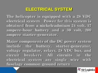
Design Specifications • Generator is rated at 600 KW, 750 KVA • 480 V, three phase, 60Hz • UPS is sized at 50 KVA and 40 KW. • 480 VAC, 3-phase, 60Hz
Design Specifications • All Panels are sized based on total Volt-Ampere (VA) of connected loads. • All the loads are summoned up throughout the entire system Electrical Panel
Diesel Generator 600KW, 750KVA 277/480 3- phase, 4W System Diagram Utility Power Transformer Fault #1 2000Amp, 277/480 3-phase,4W Fault #2 Fault #3 1600/3 1600A trip breaker Transition Transfer Switch Fault #4
400Amps 277/480 3-phase, 4w EHC 75KVA 480 – 120/208V 3-phase, 4W 75KVA 480 – 120/208V 3-phase, 4W 75KVA 480 – 120/208V 3-phase, 4W Fault #4 1600Amps, 277/480, 3-phase, 4W 400/3 400/3 400/3 400/3 ESMB Fault #5a Fault #5b Fault #5c Fault #5d 400Amps 277/480 3-phase, 4w 400Amps 277/480 3-phase, 4w 400Amps 277/480 3-phase, 4w EHA EHB 125/3 125/3 125/3 EHDP Fault #6a Fault #6b Fault #6a UPS Fault #8a Fault #8b Fault #7a Fault #7b Fault #7c
225Amps 120/208 3-phase, 4W 225Amps 120/208 3-phase, 4W 225Amps 120/208 3-phase, 4W ELA ELA ELA Watt-stopper Relay Panel Watt-stopper Relay Panel Watt-stopper Relay Panel 225/3 225/3 225/3 Fault #7a Fault #7b Fault #7c Fault #8a Fault #8b
Fault #8b Fault #8a Rectifier/ Charger Battery Cabinet Static Bypass Switch Inverter Fault #9
225Amps 120/208 3-phase, 4W 225Amps 120/208 3-phase, 4W CLA CLA 45KVA 480 – 120/208V 3-phase, 4W 45KVA 480 – 120/208V 3-phase, 4W Fault #9 225Amps, 277/480, 3-phase, 4W 70/3 70/3 Fault #10a Fault #10b 150/3 150/3 Fault #11b Fault #11a
Interrupting Rating Protective Device Available Fault Current Normal Current Operation Load Short-Circuit Operation with Inadequate Interrupting Rating Available Fault Current Short-Circuit Operation with adequate Interrupting Rating Available Fault Current
Short – Circuit Calculations IFLA = Rated Current P = Rated Power of Transformer VL-L = Secondary Line Voltage ISCA = Short-Circuit Current %Z = Rated Impedance of Transformer f = Constant Factor L = Length of Conduit n = Number of Conduit Per Phase C = Conductor Constant IS.CSYM = Short Circuit at a fault
Conclusion • Provides power distribution • Provides back up power supply • Provides uninterruptible power to server room • Provides adequate interrupting rating for protective devices