
Hybrid stability studies
E N D
Presentation Transcript
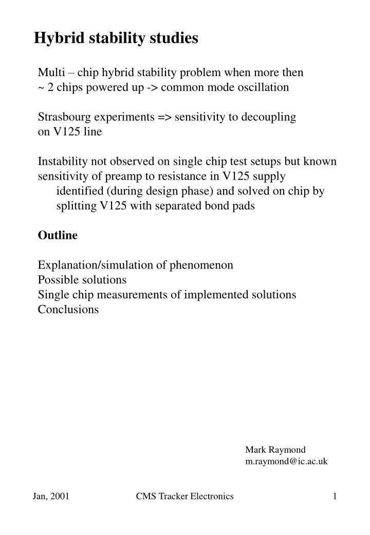
Hybrid stability studies Multi – chip hybrid stability problem when more then ~ 2 chips powered up -> common mode oscillation Strasbourg experiments => sensitivity to decoupling on V125 line Instability not observed on single chip test setups but known sensitivity of preamp to resistance in V125 supply identified (during design phase) and solved on chip by splitting V125 with separated bond pads Outline Explanation/simulation of phenomenon Possible solutions Single chip measurements of implemented solutions Conclusions Mark Raymond m.raymond@ic.ac.uk CMS Tracker Electronics
APV25s1 layout 7.1 mm 8.1 mm CMS Tracker Electronics
Preamp schematic – 1 channel V125 source follower input FET inverter stage V125 inverter stage originally included to allow maximum use of dynamic range available at shaper output required for p-strip readout inverter FET operating point determined by input FET since both device sources connected to V125 use simplified schematic CMS Tracker Electronics
Common mode stability concerns identified during design stage track resistances on-chip track resistance leads to positive feedback path around preamp -> common mode instability which gets worse with increasing number of channels CMS Tracker Electronics
On-chip solution implemented Common V125 supply on hybrid Split V125 supply on chip with separate bond pads effectively removes on-chip coupling Problem solved? Thought so but ..... CMS Tracker Electronics
Multi-chip schematic If sufficient resistance present in common V125 path then problem can re-surface (more chips => more channels) (can still occur for a single chip if resistance big enough) CMS Tracker Electronics
Simulation Approach use single channel model, put in calculated resistances for tracks but multiply values by 128 Look at dependence of transient response on external resistor in V125 supply – one chip only here Preamp output shows some increase in gain for resistances up to 10 mW equivalent (note origins of waveforms offset for clarity) CMS Tracker Electronics
Increasing common resistance still further Instability sets in for equivalent resistance >30 mW frequency similar to that observed on hybrid (~30 kHz) Interim Conclusion instability effect can be simulated strong evidence that V125 supply resistance to blame simulation may help to find solution CMS Tracker Electronics
Solutions to problem More than one – some more attractive than others reduce power plane resistance on hybrid probably end up pushing problem elsewhere Maintain V125 separation on hybrid, through connector, through mother cable, ...... where to stop? others ......... Preferred solution Concentrate here on option that appears to be most robust CMS Tracker Electronics
Proposed solution V125 supplies preamp input FETs only V125 supply to inverter stage derived from V250 via resistor probably better to supply each chip from individual resistor (~100W) to ensure current shared equally Input and inverter FET common sources completely decoupled by power supplies CMS Tracker Electronics
How does it work? Previous preamp power scheme V125 Vg V125 Current in inverter stages determined by operating point of input devices (scaled by relative widths) V250 New scheme Vg+Vt = ~V125 Vg V125 Voltage on gates of inverter transistors same as before All 128 inverter FETs operate in parallel to maintain their common sources at a threshold above gate voltages -> ~V125 => current in inverters defined by resistor value CMS Tracker Electronics
Experimental results with single chip pcb APV25s1 test pcb altered to allow inverter V125 connection to V125 or to V250 via 100W resistor response to internal calibrate pulse (16 channels) V125 V250/100W 16 cal chans remaining 112 channels no common mode subtraction used for above plots if algorithm used which calculates CM excluding channels containing signal V125 V250/100W appears to be good solution – minor drawback of power consumption in resistor CMS Tracker Electronics
Can go further ... Why not derive input FET source voltage from V250 too? Not as robust as previous solution to supply line resistance Significant increase in power consumption (~25%) But supply is now only two rails and currents balanced CMS Tracker Electronics
Experimental results 2 rail operation cal pulse response No CM subtraction CM subtract using average of channels not containing signal CM subtract using median value of all channels performance not apparently affected by supplying input FET current from V250 via 24W resistor CMS Tracker Electronics
Conclusions Stability problems encountered with 1st hybrid version understood and can be simulated Proposed solution of deriving inverter V125 supply from V250 via a resistor appears robust. Only significant drawback a minor increase in power consumption. CMS Tracker Electronics