EE444 PID Lab
EE444 PID Lab. Walter Heth Paul Zelaya EE 444 Professor Gary Hill April 24 2013. Lab Objective. Use Arduino PID Library to do the following routine: Starting from rest, travel a predefined distance in a straight line


EE444 PID Lab
E N D
Presentation Transcript
EE444 PID Lab Walter Heth Paul Zelaya EE 444 Professor Gary Hill April 24 2013
Lab Objective • Use Arduino PID Library to do the following routine: • Starting from rest, travel a predefined distance in a straight line • Turn around 180° and start a return trip, traveling back to the original starting point. • Turn 180° to start the cycle over again.
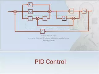
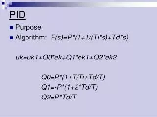
PID Overview • A Proportional-integral-derivative (PID) controller is a control scheme that allows a system to match a desired setpoint by calculating error. • Error is defined as the difference between the desired value and the current value. • Error is used to generate a control signal to the plant. • The plant will take this control signal and produce a controlling action. The goal is to have this control action reduce error over time.
PID Overview (count.) Figure 1. Generic closed loop system with PID controller (Atmel) Figure 2. Generic closed loop system with PID controller (Wikipedia)
Lab overview • Rover PID code will be uploaded to the Arduino. This will include the Arduino PID library. • The code will attempt to set the rover heading angle. The actual rover heading angle will be determined with a gyro • The gyro reading drifts significantly over time. This drift is a function of temperature. Therefore a drift correcting routine was implemented • Rover setpoint and current heading will be displayed by a Processing program in real time. • The processing program can also be used to change Kp, Kd, and Ki values • The processing program can also be used to change the setpoint.
Processing Troubleshoot • Make sure you place library files in the Processing or Arduino Library folder. Refer to section 5.1 • Importing of ControlP5 library • If ControlP5 library cannot be found, use the library manager to upload the library. Refer to section 5.2 in lab. • Processing Serial command • Refer to section 5.2 Figure 6. The correct array index must be specified in the code shown in figure 6.