Download
1 / 46
470 likes | 686 Views
What do you think about this system response?. Rotor Angle. Time. How about this response?. Rotor Angle. Time. Compare these two responses. Rotor Angle. Time. What about these responses?. Rotor Angle. Time. Compare these instabilities. Rotor Angle. Time.

E N D
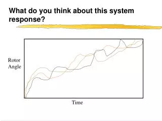
What do you think about this system response? Rotor Angle Time
How about this response? Rotor Angle Time
Compare these two responses Rotor Angle Time
What about these responses? Rotor Angle Time
Compare these instabilities Rotor Angle Time
Steady-state = stable equilibrium • things are not changing • concerned with whether the system variables are within the correct limits
Transient Stability • "Transient" means changing • The state of the system is changing • We are concerned with the transition from one equilibrium to another • The change is a result of a "large" disturbance
Primary Questions • 1. Does the system reach a new steady state that is acceptable? • 2. Do the variables of the system remain within safe limits as the system moves from one state to the next?
Main Concern: synchronism of system synchronous machines • Instability => at least one rotor angle becomes unbounded with respect to the rest of the system • Also referred to as "going out of step" or "slipping a pole"
Additional Concerns: limits on other system variables • Transient Voltage Dips • Short-term current & power limits
Time Frame • Typical time frame of concern • 1 - 30 seconds • Model system components that are "active" in this time scale • Faster changes -> assume instantaneous • Slower changes -> assume constants
Primary components to be modeled • Synchronous generators
Traditional control options • Generation based control • exciters, speed governors, voltage regulators, power system stabilizers
Traditional Transmission Control Devices • Slow changes • modeled as a constant value
FACTS Devices • May respond in the 1-30 second time frame • modeled as active devices
Kundur's classification of methods for improving T.S. • Minimization of disturbance severity and duration • Increase in forces restoring synchronism • Reduction of accelerating torque by reducing input mechanical power • Reduction of accelerating torque by applying artificial load
Commonly used methods of improving transient stability • High-speed fault clearing, reduction of transmission system impedance, shunt compensation, dynamic braking, reactor switching, independent and single-pole switching, fast-valving of steam systems, generator tripping, controlled separation, high-speed excitation systems, discontinuous excitation control, and control of HVDC links
FACTS devices = Exciting control opportunities! • Deregulation & separation of transmission & generation functions of a utility • FACTS devices can help to control transient problems from the transmission system
3 Minute In-Class Activity • 1. Pick a partner • 2. Person wearing the most blue = scribe Other person = speaker • 3. Write a one-sentence definition of "TRANSIENT STABILITY” • 4. Share with the class
Mass-Spring Analogy • Mass-Spring System
Equations of motion • Newton => F = Ma = Mx’’ • Steady-state = Stable equilibrium = Pre-fault • SF = -K x - D x’ + w = Mball x’’ = 0 • Can solve for x
Fault-on system • New equation of motion • SF = -K x - D x’ + (Mball + Mbird)g = (Mball + Mbird) x’’ • Initial Conditions? • x = xss x’ = 0
How do we determine x(t)? • Solve directly • Numerical methods • (Euler, Runge-Kutta, etc.) • Energy methods
Post-fault system • "New" equation of motion • SF = -K x - D x’ + w = Mball x’’ • Initial Conditions? • x = xc x’ = xc’
Simulation of the Pre-fault, Fault-on, and Post-fault system responses
Transient Stability? • Does x tend to become unbounded? • Do any of the system variables violate limits in the transition?
Power System Equations Start with Newton again .... T = I a We want to describe the motion of the rotating masses of the generators in the system
The swing equation • 2H d2d = Paccwo dt2 • P = T w • a = d2d/dt2, acceleration is the second derivative of angular displacement w.r.t. time • w = dd/dt, speed is the first derivative
Accelerating Power, Pacc • Pacc = Pmech - Pelec • Steady State => No acceleration • Pacc = 0 => Pmech = Pelec
Classical Generator Model • Generator connected to Infinite bus through 2 lossless transmission lines • E’ and xd’ are constants • d is governed by the swing equation
Simplifying the system . . . • Combine xd’ & XL1 & XL2 • jXT = jxd’ + jXL1 || jXL2 • The simplified system . . .
Recall the power-angle curve • Pelec = E’ |VR| sin( d ) XT
Use power-angle curve • Determine steady state (SEP)
Fault study • Pre-fault => system as given • Fault => Short circuit at infinite bus • Pelec = [E’(0)/ jXT]sin(d) = 0 • Post-Fault => Open one transmission line • XT2 = xd’ + XL2 > XT
Equal Area Criterion • 2Hd2d = Paccwo dt2 • rearrange & multiply both sides by 2dd/dt • 2 ddd2d = wo Paccdd dt dt2 H dt => d {dd}2 = wo Pacc dd dt {dt } H dt
Integrating, • {dd}2 = wo Pacc dd{dt} H dt • For the system to be stable, d must go through a maximum => dd/dt must go through zero. Thus . . .dm • wo Pacc dd = 0 = { dd }2 • H { dt } • do
The equal area criterion . . . • For the total area to be zero, the positive part must equal the negative part. (A1 = A2) • Pacc dd = A1 <= “Positive” Area • Pacc dd = A2 <= “Negative” Area dcl do dm dcl
For the system to be stable for a given clearing angle d, there must be sufficient area under the curve for A2 to “cover” A1.
In-class Exercise . . . • Draw a P-d curve • For a clearing angle of 80 degrees • is the system stable? • what is the maximum angle? • For a clearing angle of 120 degrees • is the system stable? • what is the maximum angle?