Download
1 / 24
240 likes | 272 Views
Learn how to connect and communicate between HC(S)12 microcontroller and Hitachi LCD panel for displaying data and commands efficiently.

E N D
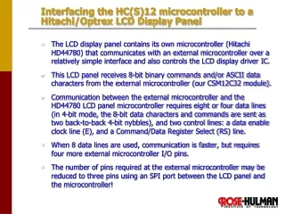
Interfacing the HC(S)12 microcontroller to a Hitachi/Optrex LCD Display Panel • The LCD display panel contains its own microcontroller (Hitachi HD44780) that communicates with an external microcontroller over a relatively simple interface and also controls the LCD display driver IC. • This LCD panel receives 8-bit binary commands and/or ASCII data characters from the external microcontroller (our CSM12C32 module). • Communication between the external microcontroller and the HD44780 LCD panel microcontroller requires eight or four data lines (in 4-bit mode, the 8-bit data characters and commands are sent as two back-to-back 4-bit nybbles), and two control lines: a data enable clock line (E), and a Command/Data Register Select (RS) line. • When 8 data lines are used, communication is faster, but requires four more external microcontroller I/O pins. • The number of pins required at the external microcontroller may be reduced to three pins using an SPI port between the LCD panel and the microcontroller!
LCD Panel Pin Description • DB7:0 – Data Bus. 8-bit data bus for both display commands AND display ASCII data. 4-bit mode transfers occur as two back-to-back 4-bit transfers on DB7:4 (DB3:0 are not connected.) • RS – Register Select. Set to 0 to indicate a command on Data Bus and 1 to indicate ASCII data on Data Bus. • RW-Read/Write. Set to 0 for write to data bus and 1 for read from data bus. We shall strap this pin to 0 V, so that it is permanently enabled for WRITE to data bus mode, in order to simplify our interface. • E – Enable (data clock). This pin must rise at least 140 ns after RS and R/W have been set up, and it must fall at least 195 ns after DB7:0 has been set up. Furthermore, DB7:0 must be held at least 10 ns after E falls. Also, E must be high for at least 450 ns.
The setting of RS and R/W allows us to: (1) write data to Display RAM (DR) (2) Read datafrom DR (3) Write commands to the display (4) read the busy flag and current value of the address counter (which controls position of character being written to DR.) We shall tie R/W low so that we will only write commands and ASCII data to the LCD panel
Note: to minimize the complexity of our interface (at the expense of slowing data transfer to the LCD panel), we shall use 4-bit mode, and we shall NOT check the LCD panel’s “Busy Flag”. Instead, we shall allow plenty of extra time for the data transfer to complete and for the “Busy Flag” to be set.
Main.asm – Main program that calls the LCD display routine “LCD_MESSAGE” in the “lcd_subroutines.asm” file. xdef Entry ;Entry point must be available to debugger xref LCD_MESSAGE ;These routines are in another file xref LCD_INIT , PLL_INIT xref __SEG_END_SSTACK ;High end of STACK area in RAM include 'mc9s12c128.inc' CodeSec: SECTION ;relocatable code section Entry: lds #__SEG_END_SSTACK jsr PLL_INIT ;Set Bus Clock to 24 MHz jsr LCD_INIT ;Init LCD Display ldx #msg1 ldab #0 ;Display Data RAM address 0 = start of 1st line jsr LCD_MESSAGE ldab #$40 ;Display Data RAM address $40 = start of 2nd line ldx #msg2 jsr LCD_MESSAGE wthr: bra wthr ConstSec: SECTION ;relocatable constant section msg1: dc.b "hello there", 0 ;ASCII null-terminated string msg2: dc.b "this is a test", 0 ;ASCII null-terminated string end
“lcd_subroutines.asm” file (to be linked with main.asm) ;***************************************************** ;Type: M68HCs12 Assembly Program for Code Warrior ;Program Name: lcd4bit_display ;Written By: Jianjian Song & Keith Hoover ;Date: October 5 2007 ;Purpose: 4-Bit Mode LCD Panel interfacing via E, RS, DB7-4 ;Display Panel Connections ;1--Vss(0V), 2--Vcc(5V), 3--Vee (0V), 4--RS = PT2, 5--R/W = 0V, ;6--E clock = PT3,11--DB4 = PT4,12--DB5 = PT5,13--DB6 = PT6 ;14--DB7 = PT7. ;**************************************************** xdef LCD_INIT ;MAKE THE FOLLOWING ;AVAILABLE TO OTHER FILE xdef LCD_DTA xdef LCD_ADDRESS xdef LCD_MESSAGE include 'mc9s12c128.inc' ;Initialize the LCD panel hardware interface LCD_DATA: EQU PTT LCD_CTRL: EQU PTT LCD_DATA_DIRECTION EQU DDRT LCD_CTRL_DIRECTION EQU DDRT DATA_OUTPUT EQU %11110000
lcd_subroutines.asm, continued CTRL_OUTPUT EQU %00001100 E: EQU %00001000 ;E = MASK TO ACCESS PT3 = LCD CONTROL LINE E RS: EQU %00000100 ;RS = MASK TO ACCESS PT2 = LCD CONTROL LINE RS DataSec: SECTION TIME: DS 2 ;delay time variable CodeSec: SECTION ;************************************************************* ;LCD_INIT subroutine ;Initializes LCD Display according to manufacturer's directions ;************************************************************ LCD_INIT: BSET LCD_DATA_DIRECTION,DATA_OUTPUT ;MAKE PT7:4 DRIVE LCD DB7:4 DATA INPUTS BSET LCD_CTRL_DIRECTION,CTRL_OUTPUT ;MAKE PT2 & PT3 DRIVE LCD RS ;AND E CONTROL LINES BCLR LCD_CTRL,E ; Set E to 0 BCLR LCD_CTRL,RS ; Set RS=0 to select instruction entry mode BCLR LCD_DATA,DATA_OUTPUT ;Set 4-bit data output to 0 ; 1st wait for 20 milliseconds (minimum of 15 ms) MOVW #400, TIME JSR VAR_DELAY
lcd_subroutines.asm, continued ; Note: the LCD display always powers up in 8-bit transfer mode, but even though all 8 ; bits are transferred into the display module when E falls, the bottom 4 bits of each ; byte are IGNORED when an INIT command is sent, so it is OK that the bottom 4 bits of the ; LCD panel data bus (DB3:0) are not connected to anything! ; send the 8-bit mode INIT command 3 times in a row (as recommended by manufacturer) ; Here is the first INIT command LDAB #$30 JSR SEND4bits ; wait for 10 ms ( minimum of 4.1 ms) before sending next INIT command. MOVW #200, TIME JSR VAR_DELAY ; send second INIT command LDAB #$30 JSR SEND4bits; 3rd wait for 1 millisecond (minimum of 0.1 ms) MOVW #20, TIME
lcd_subroutines.asm, continued JSR VAR_DELAY LDAB #$30 JSR SEND4bits ; Send third INIT command MOVW #20, TIME JSR VAR_DELAY ; Now send a fourth init command so that it changes the data transfer mode ; from 8-bits all at once to the 4-bit transfer mode, in which an 8-bit ; byte is transferred over the most-significant 4 bits of the display panel ; data bus (DB7:4)by two back-to-back calls to SEND4bits LDAB #$20 JSR SEND4bits MOVW #20, TIME JSR VAR_DELAY ; This command sets data transfer mode to 4-bit mode, so now a full 8-bits are transferred ; by two back-to-back calls to SEND4bits LDAB #$28 JSR SENDBYTE ; Function Set Command Format: 0 0 1 DL N F * * ; We just sent: 0 0 1 0 1 0 0 0 ; DL=0 => 4-bit mode, ; N=1 => 1/8 duty cycle ; F=0 => 5 X 7 dot font LDAB #$08 JSR SENDBYTE ; Display OFF command LDAB #$01 JSR SENDBYTE; ;Clear display and return home
lcd_subroutines.asm, continued LDAB #$06 JSR SENDBYTE ;Entry mode set command format: 0 0 0 0 0 1 I/D S ;I/D = 1 => Increment display addr ptr. ;S = 0 => Do not shift (scroll) display LDAB #$01 JSR SENDBYTE; ;Clear display and return home LDAB #$0F JSR SENDBYTE ; Display ON command RTS ;********************************************************
lcd_subroutines.asm, continued ;******************************************************************* ; Subroutine SEND4bits drives 4-bit data out on upper 4 bits of LCD data port ; then, after > 1 us delay, raises the E line, then, after > 1 us delay ; lowers the E line to complete the write cycle, then, after > 1 us delay ; returns. ;******************************************************************* SEND4bits: PSHB ANDB #$F0 LDAA LCD_DATA ; Load high 4 bits of accum B into LCD_DATA (PTT), but ANDA #$0F ; leave the bottom 4 bits untouched (since E and RS are STAA LCD_DATA ; in the bottom 4 bits!) ORAB LCD_DATA STAB LCD_DATA ;DRIVE 4-BIT DATA OUT ON UPPER 4 BITS OF DATA PORT JSR WT5US BSET LCD_CTRL,E ; RAISE E LINE JSR WT5US ; LET IT STAY HIGH FOR > 1 US BCLR LCD_CTRL,E ; LOWER IT MOVW #2, TIME ; Wait 1 us for BF flag JSR VAR_DELAY PULB RTS
; Subroutine WT5US waits approximately 5 us, then returns ;******************************************************** WT5US: PSHY ;WAIT ABOUT 5 US LDY #10 WTHERE: DBNE Y,WTHERE PULY RTS ;**************************************************************** ; Subroutine: VAR_DELAY ; Delays for a period of time equal to Tdelay = TIME*50 microseconds ; This assumes a 24MHz bus clock, and that the RAM location ; "TIME" is a input variable that must be loaded prior to calling VAR_DELAY ; Note: The inner loop delay time = (4*300+4)*(1/24MHz)=50 microseconds ;**************************************************************** LOOPS EQU 2400 VAR_DELAY: PSHX ; 2 cycles PSHY ; 2 cyles LDY TIME ;3 cycles LP1: LDX #LOOPS ; 2 cycle LP2: DEX ; 1 cycle BNE LP2 ; 3 cycles DEY ; 1 cycles BNE LP1 ; 3 cycles PULY ; 3 cycles PULX ; 3 cycles RTS ; 5 cycles
lcd_subroutines.asm, continued ;********************************* ; SUBROUTINE: SENDBYTE ; Writes a byte in Accumulator B to LCD panel in "4-bit transfer" mode ; via two back-to-back 4-bit writes over bits DB7:4) ;********************************* SENDBYTE: PSHB ; send higher nibble out on DB7:4 first JSR SEND4bits MOVW #2,TIME ;Wait 100 us after first 4-bit transfer cycle JSR VAR_DELAY PULB PSHB ; rotate lower nibble up into B7:4 ROLB ROLB ROLB ROLB ; send lower nibble out on DB7:4 last JSR SEND4bits MOVW #2,TIME JSR VAR_DELAY ;Wait 100 us after second 4-bit transfer cycle PULB RTS
lcd_subroutines.asm, continued ;********************************* ; SUBROUTINE: LCD_ADDRESS ; Sends an address in Accumulator B to LCD and thereby positions cursor ; to any arbitrary position on display. Addr $00...$17 => 1st row of display ; Addr $40...$57 => second row of display. ;********************************* LCD_ADDRESS: PSHB BCLR LCD_CTRL, RS ; Place LCD in command mode (RS = 0) ORAB #$80 ; Set MSB so the DDR address set command is sent JSR SENDBYTE PULB RTS ;********************************* ; SUBROUTINE: LCD_DTA ; displays 8-bit ASCII-coded character in B register ;********************************* LCD_DTA: PSHB BSET LCD_CTRL, RS ; Place LCD in ASCII CHARACTER DISPLAY mode JSR SENDBYTE ; (RS = 1) PULB RTS
lcd_subroutines.asm, continued ;********************************* ; SUBROUTINE: LCD_MESSAGE(B,X) ; Displays an ASCII text message to LCD. ; Accumulator B contains the address to write to ; For 2 x 24 display, Line 1: 0 - 0x17, Line 2: 0x40..0x57 ; X register contains starting address of the ASCII-coded text message ; The text message must be terminated in an ASCII NULL ($00) character. ;********************************* LCD_MESSAGE: PSHB PSHX JSR LCD_ADDRESS ; send address to LCD NEXT: LDAB 0, X ; load character BEQ DONE ; exit if character is 0 (ASCII Null) JSR LCD_DTA ; send character in Accumulator A to LCD INX BRA NEXT DONE: PULX PULB RTS END