Download
1 / 1
10 likes | 168 Views
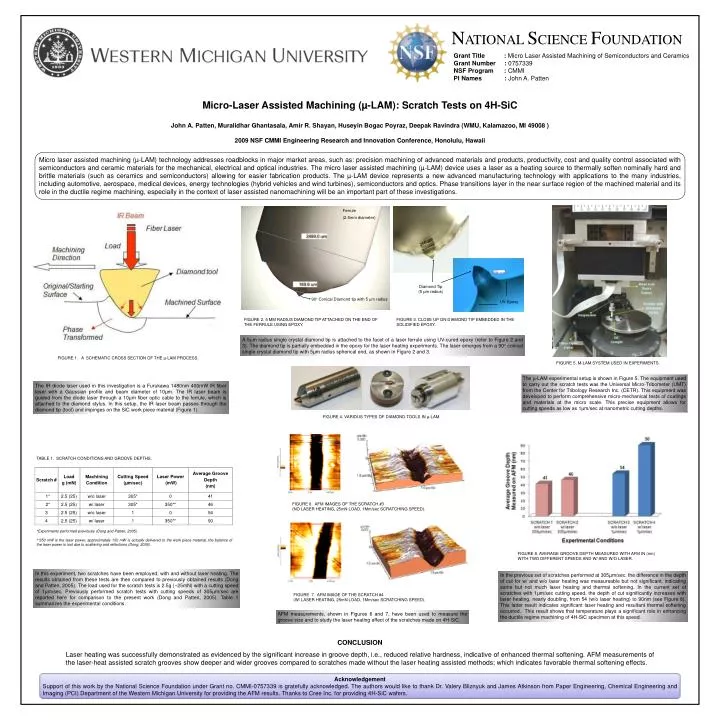
Ferrule (2.5mm diameter). 90° Conical Diamond tip with 5 m radius. UV-Epoxy. N ATIONAL S CIENCE F OUNDATION. Grant Title : Micro Laser Assisted Machining of Semiconductors and Ceramics Grant Number : 0757339 NSF Program : CMMI

E N D
Ferrule (2.5mm diameter) • 90° Conical Diamond tipwith 5 m radius UV-Epoxy NATIONAL SCIENCE FOUNDATION Grant Title : Micro Laser Assisted Machining of Semiconductors and Ceramics Grant Number : 0757339 NSF Program : CMMI PI Names : John A. Patten Micro-Laser Assisted Machining (µ-LAM): Scratch Tests on 4H-SiC John A. Patten, Muralidhar Ghantasala, Amir R. Shayan, Huseyin Bogac Poyraz, Deepak Ravindra (WMU, Kalamazoo, MI 49008 ) 2009 NSF CMMI Engineering Research and Innovation Conference, Honolulu, Hawaii Micro laser assisted machining (µ-LAM) technology addresses roadblocks in major market areas, such as: precision machining of advanced materials and products, productivity, cost and quality control associated with semiconductors and ceramic materials for the mechanical, electrical and optical industries. The micro laser assisted machining (µ-LAM) device uses a laser as a heating source to thermally soften nominally hard and brittle materials (such as ceramics and semiconductors) allowing for easier fabrication products. The µ-LAM device represents a new advanced manufacturing technology with applications to the many industries, including automotive, aerospace, medical devices, energy technologies (hybrid vehicles and wind turbines), semiconductors and optics. Phase transitions layer in the near surface region of the machined material and its role in the ductile regime machining, especially in the context of laser assisted nanomachining will be an important part of these investigations. 250 µm Diamond Tip (5 μm radius) • FIGURE 2.5 µm radIus dIamond tIp attached on the end of the ferrule usIng epoxy. • FIGURE 3. Close up on diamond tip embedded in the solidified epoxy. A 5m radius single crystal diamond tip is attached to the facet of a laser ferrule using UV-cured epoxy (refer to Figure 2 and 3). The diamond tip is partially embedded in the epoxy for the laser heating experiments. The laser emerges from a 90 conical single crystal diamond tip with 5μm radius spherical end, as shown in Figure 2 and 3. FIGURE 1. A SCHEMATIC CROSS SECTION OF THE µ-LAM PROCESS. • FIGURE 5. µ-LAM system used in experiments. The µ-LAM experimental setup is shown in Figure 5. The equipment used to carry out the scratch tests was the Universal Micro-Tribometer (UMT) from the Center for Tribology Research Inc. (CETR). This equipment was developed to perform comprehensive micro-mechanical tests of coatings and materials at the micro scale. This precise equipment allows for cutting speeds as low as 1µm/sec at nanometric cutting depths. The IR diode laser used in this investigation is a Furukawa 1480nm 400mW IR fiber laser with a Gaussian profile and beam diameter of 10μm. The IR laser beam is guided from the diode laser through a 10µm fiber optic cable to the ferrule, which is attached to the diamond stylus. In this setup, the IR laser beam passes through the diamond tip (tool) and impinges on the SiC work piece material (Figure 1). FIGURE 4. VARIOUS TYPES OF DIAMOND TOOLS IN μ-LAM. TABLE 1. SCRATCH CONDITIONS AND GROOVE DEPTHS. FIGURE 6. AFM IMAGES OF THE SCRATCH #3 (No laser heating, 25mN load, 1µm/sec Scratching Speed). *Experiments performed previously (Dong and Patten, 2005). **350 mW is the laser power, approximately 150 mW is actually delivered to the work piece material, the balance of the laser power is lost due to scattering and reflections (Dong, 2006). • FIGURE 8. AVERAGE GROOVE DEPTH MEASURED WITH AFM IN (nm) WITH TWO DIFFERENT SPEEDS AND W/ AND W/O LASER. In this experiment, two scratches have been employed; with and without laser heating. The results obtained from these tests are then compared to previously obtained results (Dong and Patten, 2005). The load used for the scratch tests is 2.5g (~25mN) with a cutting speed of 1µm/sec. Previously performed scratch tests with cutting speeds of 305µm/sec are reported here for comparison to the present work (Dong and Patten, 2005). Table 1 summarizes the experimental conditions. In the previous set of scratches performed at 305µm/sec, the difference in the depth of cut for w/ and w/o laser heating was measureable but not significant, indicating some but not much laser heating and thermal softening. In the current set of scratches with 1µm/sec cutting speed, the depth of cut significantly increases with laser heating, nearly doubling, from 54 (w/o laser heating) to 90nm (see Figure 8). This latter result indicates significant laser heating and resultant thermal softening occurred. This result shows that temperature plays a significant role in enhancing the ductile regime machining of 4H-SiC specimen at this speed. FIGURE 7. AFM IMAGE OF THE SCRATCH #4 (w/ laser heating, 25mN load, 1µm/sec Scratching Speed). AFM measurements, shown in Figures 6 and 7, have been used to measure the groove size and to study the laser heating effect of the scratches made on 4H-SiC. CONCLUSION Laser heating was successfully demonstrated as evidenced by the significant increase in groove depth, i.e., reduced relative hardness, indicative of enhanced thermal softening. AFM measurements of the laser-heat assisted scratch grooves show deeper and wider grooves compared to scratches made without the laser heating assisted methods; which indicates favorable thermal softening effects. Acknowledgement Support of this work by the National Science Foundation under Grant no. CMMI-0757339 is gratefully acknowledged. The authors would like to thank Dr. Valery Bliznyuk and James Atkinson from Paper Engineering, Chemical Engineering and Imaging (PCI) Department of the Western Michigan University for providing the AFM results. Thanks to Cree Inc. for providing 4H-SiC wafers.