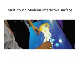
Multi-Touch Navigation Engine
This presentation by Team Extra Touch explores a Multi-Touch Navigation Engine designed for advanced touch detection and data processing. It details the innovative methods used to handle "phantom touches" and improve accuracy in detecting touch points, contrasting with previous models limited by low resolution. The process involves parsing sensor data, applying bilateral interpolation, and utilizing a Voronoi skeleton algorithm for shape recognition. The flowcharts and algorithms presented showcase the usability of this system for interactive devices and applications, aiming for efficient channel assignment and data output.


Multi-Touch Navigation Engine
E N D
Presentation Transcript
Multi-Touch Navigation Engine • Detailed Design Review Presented by Team Extra Touch: Chris Jones Shuopeng Yuan Nathan Wiedeback 1
Make it interesting… Challenge Solution Compare to previous frame Low resolution (240 x 180) for proof-of-concept Make each stage’s data available at the output Get help! • Phantom touches • “[40K] ought to be enough for anybody!” • Need “tap points” for intermediate data • We’re not really programmers…
Serial Stream Parser 74 byte “packets” from the screen Interrupt-driven I/O on ARM -- until an entire packet received Then process it to get 32 sensor values, average, etc. Normalize by subtracting the lowest value from each Variations of ~100-200 • (Little-endian) • Average: 0x488B = 18,571 • First sensor: 0x4886 = 18,566
Interpolator Input: 32 x 2-byte sensor levels Output: “Image” frame -- n x m x 1 bit pixel array Proof-of-concept: 240 x 180 (memory constraints) Find intersection points of sensors (16 x 16) Interpolate linearly based on distance – first in X, then in Y (bilinear) Set a threshold and discretize at the end Each pixel ends up as a 1 or a 0 Image source: Wikipedia
Phantom Filter Input: Frame Output: Filtered frame (240 x 180 x 1 bit) Intersections method -> phantom touches Remember what was touched first – i.e., save and compare to the last frame Proof of concept -- only the simple case covered
The X-Y Coordinates in separate arrays x y 7 3 12 3 6 4 14 4 5 5 15 5 6 6 15 6 6 7 15 7 6 8 14 8 6 9 14 9 6 10 14 10 6 11 14 11 7 12 13 12 7 13 14 13 7 14 13 14 7 15 13 15 7 16 13 16 8 17 13 17 9 18 12 18 x y 32 3 34 3 31 4 35 4 31 5 34 5 x y 39 11 40 11 38 12 41 12 39 13 41 13
6 5 4.5 6.5 2.5 7.5 -0.5 8.5 -4.5 9.5 -9.5 10.5 8 5 9.5 5.5 10 6.5 10.1053 6.65789 10 7.5 9.5 9.5 7.5 10.5 5.5 12.5 3.5 13.5 0.5 14.5 -3.5 15.5 10 8.5 10 12.5 10.0833 13 10 14.5 8.5 15.5 10 13.5 10 9.33333 10.3 15.5 10 14.5 10 14.75 10.3333 15.6667 10.5 16 11.5 16.5 11.75 6 10 8.5 10 9.33333 10.5 9.5 12.5 10.5 14 12 13 13 14.5 14.5 16.5 15.5 19.5 16.5 13.5 5.5 12.5 6 13.5 6.5 15.5 8.5 17.5 9.5 20.5 10.5 26.5 12 Voronoi Skeleton Algorithm(The actual result)
Slope algorithm If a skeleton is linear, according to geometry, angle a1 = a2 = a3 = a4 Therefore, only linear shaped skeleton can pass this filter. To the touch panel application, it means only the side of a palm instead of a palm shape can pass.
Data In: Center coordinates (X,Y) Processing: Data gets transformed into a 2d array, and the compared against each channel frame to determine its channel. Channel frames are defined before compile. Data Out: (X,Y) coordinates with channel data attached. Details: Aiming for 2 channels initially Should be simple to add channels in the final iteration. Channel Assignment
Channel Assignment - Visual Representation Channel 0 Frame Channel 1 Frame Input: Coordinate Data (3,3) touched Channel 2 Frame Output to PC: Coordinates 3,3 Channel 2 We have a match at Channel 2!