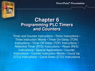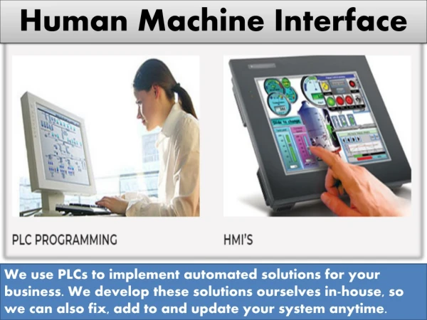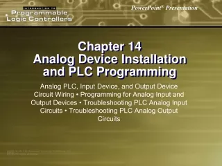
PLC Programming
6. PLC Programming. Objectives. List the rules for creating a PLC ladder logic diagram. Convert a relay logic diagram to a PLC ladder logic diagram. Create ladder logic diagrams when the PLC is in the offline mode. Download PLC ladder logic diagrams and test them on a trainer. Objectives.

PLC Programming
E N D
Presentation Transcript
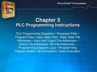
6 PLC Programming
Objectives • List the rules for creating a PLC ladder logic diagram. • Convert a relay logic diagram to a PLC ladder logic diagram. • Create ladder logic diagrams when the PLC is in the offline mode. • Download PLC ladder logic diagrams and test them on a trainer.
Objectives • Use the force instruction for troubleshooting. • Create and print program reports. • Save and open ladder diagram project files.
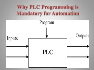
Creating PLC Ladder Logic Diagrams from Relay Logic Diagrams • To create relay logic diagrams, use input device symbols and output device symbols. • Input and output port addresses are assigned to each input and output device. • Each row is called a rung.
Creating PLC Ladder Logic Diagrams from Relay Logic Diagrams (Cont.) • Rule 1. Place a contact in the upper-left corner of the ladder logic diagram. • Rule 2. Place the coil at the end of the rung.
Creating PLC Ladder Logic Diagrams from Relay Logic Diagrams (Cont.) • Rule 3. All contacts must be placed horizontally. • Rule 4. Outputs cannot be connected in series with other outputs.
Creating PLC Ladder Logic Diagrams from Relay Logic Diagrams (Cont.) • Rule 5. Program execution flow must be from left to right. • Rule 6. Place the rung numbers on the left side of each rung.
Rung Comments • Placed on the top of each rung. • Describe major function of following rungs. • Specify location of each contact associated with a coil. • Place contact next to the coil the number of the rung the associated contact is on.
Programming Ladder Logic Diagrams with NO and NC Switches • After constructing the relay logic diagram: • Assign addresses to each input and output device. • Connect input/output devices to the PLC ports. • Create PLC ladder diagram.
Programming Ladder Logic Diagrams with NO and NC Switches (Cont.) • PLC is in offline programming mode while ladder diagram is created. • Offline mode: • Mode where the PLC ladder logic diagram can be created.
Programming Ladder Logic Diagrams with NO and NC Switches (Cont.)
Programming Ladder Logic Diagrams with NO and NC Contacts • Software allows set up of the I/O configuration.
Programming Ladder Logic Diagrams with NO and NC Contacts (Cont.) • Slot zero: • Always reserved for the PLC processor. • Slot one: • Houses a sixteen port 120 VAC input module. • Slot two: • Houses a sixteen port 120 VAC output module.
Programming Ladder Logic Diagrams with NO and NC Contacts (Cont.) • Input/output connections of the Allen-Bradley Modular SLC 503 PLC.
Program Scan • PLC program execution flow on each rung is from left to right. • From the top rung to the bottom rung, moving through the entire PLC ladder logic diagram. • Operational Scan Rate: • Time required to execute the PLC ladder diagram once.
PLC Program Scan Time • PLC ladder logic diagram instructions: • Scanned from the instruction in the upper-left corner. • Ends with the instruction on the lower- right corner. • After last instruction in the lower-right corner, scanning restarts.
PLC Program Scan Time (Cont.) • Output energize (OTE): • Output port connected to an output device. • Output latch (OTL) and output unlatch (OTU): • Used for latch/unlatch instructions. • One-shot rising (OSR): • One-shot output instruction used to generate a one-shot pulse.
PLC Operational Cycle • Input scan: • Processor reads input ports and updates input status table. • Programscan: • Processor executes PLC program and updates output status table. • Outputscan: • Output status table values transferred to output terminals.
Scanning a Rung • Input and output addresses are updated. • Sometimes, specific inputs or outputs may not be updated in time. • Immediate input with mask (IIM). • Immediate output with mask (IOM).
Project Tree Area • Divided into: • Program Files. • Data Files. • Three program file icons in the Program Files area.
Program Files • SYS0 program file: • Used by PLC processor to keep track of its internal register settings. • Not available to RSLogix 500 user. • SYS1 program file: • Reserved. • Not available to RSLogix 500 user.
Main Program File(LAD2) • Holds the main PLC ladder logic diagram. • PLC project: • May be more than one program file.
Subroutine Program Files • May be several in addition to the main program file. • Called on or accessed from the main program file. • Selecting a main program file or a subroutine file in the project tree area: • Ladder logic diagram is displayed in ladder view area.
Input (I) Output (O) Status (S2) Timer (T4) Counter (C5) Control (R6) Integer (N7) Bit (B3 and B10) Data Files
Data Files (Cont.) • Input (I): • Inputs can be examine if open (XIO)or examine if closed (XIC). • Output (O): • In the Allen-Bradley Fixed SLC 500 PLCs, eight output ports in module zero.
Status (S2) • Holds the flag or status bits of the ladder logic diagram. • If a central processing unit fault is generated in the PLC, click this icon. • Find fault indicator status bit. • Read the reason the message was generated. • Correct the program to solve the fault condition.
Timer (T4) • Holds information related to the number of timers used in the ladder logic program. • Depending on the size of the PLC RAM, there could be timers with addresses from T4:0 to T4:255. • A PLC ladder diagram can have access to 256 timers. • Number of timers is limited due to lack of enough RAM memory in the PLC.
Counter (C5) • Holds information related to counters that can have any address from C5:0 to C5:255. • Number limited due to the lack of RAM memory in the PLC.
Control (R6) • Control file (R6) holds 256 words (R6:0 to R6:255) used as control registers. • Control registers are used with sequencer and shift register instructions. • Registers R6:0 to R6:255 can hold valuable information related to the sequencer and shift register instructions.
Integer (N7) • Holds 256 words (N7:0 to N7:255) that can be used as temporary storage integer registers.
Bit (B3 and B10) • Each hold 256 words (B3:0 to B3:255 and B10:0 to B10:255). • Used by advance PLC instructions such as bit shift and sequencer instructions. • All Allen-Bradley SLC 500 series Programmable Logic Controllers have 16-bit registers.
Programming Ladder Logic Diagrams with Latch and Unlatch Instructions PLC ladder diagram for the relay logic diagram.
Loading and Troubleshooting PLC Ladder Diagrams in Run Mode • PLC ladder logic diagram will be loaded into the PLC. • PLC will be placed in the run modeand online monitor mode.
Run Modes • Offline mode. • Online mode.
Run Modes (Cont.) • When PLC is in run and online monitor mode: • Run mode icon on the top of the screen will start rotating along its vertical axis. • Two vertical rails in the ladder logic diagram will be highlighted.
Forced Condition Mode • Method of testing the PLC system without actually closing or opening input devices. • Keys on the computer keyboards are pressed to test the program. • Force condition must be used with extreme caution. • Allows a programmer to turn outputs on and off without actually touching the input/output devices.
Forced Condition Mode (Cont.) • Place PLC in the offline mode and create the ladder logic diagram displayed. • Download program into PLC. • Place PLC in run/online monitor mode. • Even though the force instruction is a powerful tool for troubleshooting, using the force instruction in an industrial plant has the potential of causing fatal accidents.
Creating and Printing PLC Program Reports • Different report options available. • Configure the printer and its settings. • Preview reports that are ready to be printed and print them. • PLC manufacturer’s programming software will have similar report options.
Creating and Printing PLC Program Reports (Cont.) • Seven commands for creating and printing PLC reports found under the File menu: • Print View. • Print Preview. • Report Options. • Report Preview. • Print Report. • Printer Setup. • Page Setup.
Report Options • General. • Data Files. • Program Files. • Special. • Database. • Miscellaneous Layout Options.
General Report • Title Page. • Processor Information. • I/O Configuration. • Channel Configuration. • Custom Data Monitor. • Cross Reference. • Multipoint List.
Title Page Report • Prints the RSLogix 500 name and the Rockwell software logo. • Printing this page requires a lot of ink. • Therefore, do not select this option.
Processor Information Report • Contains the name and type of processor used in the PLC system. • Know the type of PLC used with your lab station. • Do not need to select this option either.
I/O ConfigurationReport • Number of slots available on the PLC. • Which slots are configured to be used and how many ports each module in the expansion slot has. • Printouts of the number of input/output devices used.
Channel ConfigurationReport • Lists the controller channel number used for the communication between the PLC and the computer. • The PLC is assigned to station or node zero. • Configure the AB_PIC-1 (Allen-Bradley Peripheral Interface Connector) device driver that uses channel one.
Channel One • RJ-45 connection terminal. • RJ-45 type terminal looks similar to the RJ-11 telephone jack terminal, except the RJ-45 is larger than the RJ-11 terminal. • Always used for connecting the 1747-PIC communication interface device to the PLC and the computer.
Channel Zero • Could also be used for connecting peripheral devices. • Barcode reader or a printer directly to the SLC 502, SLC 503, SLC 504, and SLC 505 PLC systems. • Channel zero uses the RS 232C (Recommended Standard 232C) standard channel available on these PLC systems.