Download
1 / 32
320 likes | 411 Views
Detailed progress update on the experimental layout, beam instrumentation, solenoid power supply, and safety issues at CERN. Includes information on system design, cryogenics, access shafts, and installation schedules.

E N D
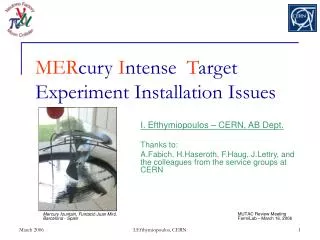
MERcury Intense Target Experiment Installation Issues I. Efthymiopoulos Thanks to: A.Fabich, H.Haseroth, F.Haug, J.Lettry, and the colleagues from the service groups at CERN MUTAC Review Meeting FermiLab – March 16, 2006 I.Efthymiopoulos, CERN
The experimental layout Progress update Experiment sub-systems Cryogenics Solenoid power supply Safety issues Solenoid and cryogenics review Access and interlocks Transport and installation Budget Schedule … and a short update on Beam parameters – pulse list Beam instrumentation Outline I.Efthymiopoulos, CERN
The Experimental Layout • Good progress over the last months • location of experiment (solenoid) and the beam line elements in the TT2A tunnel defined • a preliminary rack allocation of the experiment services in the TT2 tunnel is proposed • Detailed AutoCAD drawings of the TT2 and TT2A tunnels are now available • Include all the shielding walls and services for the nTOF beam and target already installed in the area • Used already to define the passage of the cryogenics exhaust line into TT10 and the location of the cable passage holes between TT2/TT2A tunnels I.Efthymiopoulos, CERN
The Experimental Layout N2 Exhaust line Exp. racks Material access shaft • Upstream beam elements (new) • Quadrupoles for final focusing • Collimator • Beam profile measurement Beam dump Solenoid & Hg loop I.Efthymiopoulos, CERN
The Experimental Layout Upstream hole: OD=30cm for cryogenics Cable passages • Allow short passage for cables and services between TT2 and TT2A tunnels • Reduce cost and complexity • The hole direction is optimized to minimize radiation leakage to TT2 tunnel • Could be filled with sandbags after the installation of the cables if radiation is an issue OD=20cm for optical diagnostics OD=20cm for Hg-loop piping I.Efthymiopoulos, CERN
The Experimental Layout I.Efthymiopoulos, CERN
The Experimental Layout Access shaft & Surface installation for cryogenics Cryogenics assembly and surface tests MERIT Offices & Control Room I.Efthymiopoulos, CERN
Cryogenics Aim: • Provide LN2 to cool the solenoid at 80K • Readout and control according to CERN standards • Guarantee safety of operations • Collaboration between RAL & CERN • Project engineer: F.Haug/CERN Status: • System design completed including instrumentation and safety valves • Gas N2 exhaust line to TT10 installed I.Efthymiopoulos, CERN
Cryogenics Warm gas exhaust line to TT10 N2 gas bottles and heat exchanger Cold valve box LN2 dewar LN2 transfer line Proximity cryogenics: CVB and Heat Exchanger Transfer lines Solenoid I.Efthymiopoulos, CERN
Cryogenics Process & Instrumentation Diagram F.Haug - CERN I.Efthymiopoulos, CERN
Cryogenics • After several iterations, the Specification document for DVB is now available • Tendering will be done by RAL • Production on the critical path • Procurement of other components ongoing in parallel • Valves, control equipment Schedule: • System assembly at CERN • Commissioning at surface (bat.180) in Autumn 2006 • Installation in the tunnel to follow I.Efthymiopoulos, CERN
Solenoid Power Supply Aim: • Provide power for the solenoid in “pulsed” mode: 7kA;700V / 30 min • Recuperate the power supply used for the SPS extraction to the West Area • Work done by CERN/AB-PO group Status: • Power supply installed in bat.193 • Refurbishment started – will be completed by October 2006 • AC transformer installed • Associated AC circuitry refurbishment to be done for the 18kV cell • Cabling: • DC cabling {power supply – solenoid} installed • 6 400 mm2 Al cables - air cooled • AC cabling partially done I.Efthymiopoulos, CERN
Solenoid power supply Power Supply in 193 building AC Transformer Power Supply in 193 building G.LeGedoc – AB/PO I.Efthymiopoulos, CERN
Safety issues • MERIT Presentations in: • AB Installation Committee (ABIC) • discussed interface with PS/SPS and CERN services teams • permission to work in TT2/TT2A tunnel during PS/SPS operation • AB Safety Committee(ABSC) • Presented safety structure of the experiment and proposal for review program of various components • ISIEC form for the experiment • Define safety structure and identify safety issues • Initiated reviews of the various systems • Started with the Solenoid and Cryogenics System I.Efthymiopoulos, CERN
Safety Initial Safety Information for Experiments at CERN - ISIEC • CERN is informed about all safety particularities of MERIT • MERIT Safety structure: • H.Kirk & K.McDonald overall responsible as spokespersons • A.Fabich as GLIMOS • General Liaison in Matters of Safety • Information on safety issues for the experiment under CERN/EDMS structure • Also available from the experiment web pages: http://cern.ch/merit I.Efthymiopoulos, CERN
Safety issues Solenoid and Cryogens Review • Held @CERN in February 2006 • Review panel from CERN safety and cryogenic system experts • Safety officials as observers • Report available http://edms.cern.ch/document/710659 I.Efthymiopoulos, CERN
Safety issues …Solenoid and Cryogenics Review – Major remarks • Provide documentation for solenoid fabrication • Including x-ray validation of the welds • Proof that ASME standards are respected • And corresponding vessel validation is made • Important to keep good record of the tests made and findings during the MIT tests • Safety valves and operating pressure for solenoid to be defined • Process flow diagram for the cryogenics operation should be defined in detail I.Efthymiopoulos, CERN
Safety issues Next steps: • Reply by June to the issues addressed by the S&C Review • Schedule reviews in the coming months for: • The Hg-loop system • Transport and installation at CERN I.Efthymiopoulos, CERN
Safety issues Access and interlock • Access in TT2/TT2A tunnels possible when PS/SPS in operation • Limited access as in other exp. areas • Card reader for personnel access • Interlock conditions defined: • Access interlock: no beam magnet off ODH detection • Magnet power supply interlock cryogenics system I.Efthymiopoulos, CERN
Transport & Installation • Studies on how to transport the solenoid started • Passage around TT2/TT2A junction always critical I.Efthymiopoulos, CERN
Beam request – pulse list • Based on pulse list July 2005 • http://proj-hiptarget.web.cern.ch/proj-hiptarget/default/Documents/subsystems/ProtonBeam/pulselist.xls • Total dose limited to 3 1015 protons on target. Beam parameters: • Nominal momentum 24 GeV/c • Intensity/bunch – baseline: harmonic 16 (i.e. 16 buckets in PS, Dt=125ns) • 2-2.5 1012 protons / bunch • total maximum ~30 1012 protons/pulse • Pulse length up to 20 ms possible (beyond 2 ms switch to 14 GeV/c) Next steps: • MD time in 2006 assigned • To address the most critical configurations – priorities should be defined • Set-up time at the beginning of 2007 may be required to achieve the highest intensities I.Efthymiopoulos, CERN
dn PROBE: 2 bunches = 5*1012 protons Beam setup for Cavitation Studies • h16 beam operates in bunch pairs • Bunch pairs located in bucket n and n+1 • dnexperiment = 0,2,4,6,8, 16,18,20,22,24, 32,40, 48,56, ... • Inhomogeneous intensity distribution causes intensity limits • MD dates scheduled towards the end of 2006 – profit from development of CNGS beams with similar (high) intensities PUMP: 6 bunches = 15*1012 protons n=1 Possible Chosen I.Efthymiopoulos, CERN
3 Monitor types considered Based on beam properties to be measured MTV screens “almost” readily available Minor effort Minimum budget SEM-grid None available - needs new construction Costly: >50 kChF Manpower these days very little at CERN Wire scanner “Slow” measurement Baseline: MTV screens Transverse beam parameters Position & spot size MTV screens Direction 2 MTV screens & collimator Divergence not a direct measurement Rely on beam simulations Estimate from spot size monitors Longitudinal beam parameters Measured by pick-ups in the PS & TT2 line upstream of MERIT Log values and make available the information for the MERIT collaboration Parameters measured: Bunch length Bunch spacing Pulse length Intensity Beam profile measurement I.Efthymiopoulos, CERN
Installation Schedule • Target date: November 2006! • Ready to receive and install the solenoid and Hg-loop into the tunnel • Infrastructure in the tunnel has to be finished beforehand • Installation and commissioning of solenoid and Hg-loop only at the TT2A tunnel • Working schedule available taking into account: • Installation delays: manpower, tendering, ordering, ... • Access limitations due to PS/SPS operation in 2006 I.Efthymiopoulos, CERN
Schedule at CERN I.Efthymiopoulos, CERN
Budget CERN Code status – March 2006 • Total credited: 700 CHF (560 USD) • Committed from BNL: 320 kCHF • Spent to date: 85 kCHF • Pipeline : 25 kCHF I.Efthymiopoulos, CERN
Conclusions • Good of progress on MERIT installation issues • Experiment layout defined • Power supply, DC cabling, TT10 vent line, cable passages, • Important progress on Safety issues • ISIEC form and presentation in relevant committees • Review of solenoid and cryogenics systems • Integration schedule on track • Tendering & construction of cryogenics DVB on critical path • Cryogenics must proceed to schedule • The goal remains to have beam at the startup in 2007 I.Efthymiopoulos, CERN
More slides I.Efthymiopoulos, CERN
Proposition for Priorities General approach • Repeat each parameter configuration twice • Increase intensity to moderate 1.5*1013 protons/pulse • Do basic program, MHD first • Each proton pulse configuration is performed at B=15 T (solenoid) and B=0 T (horn) • Consider effort for PS operation to change settings 0. beam setup • MHD • beam position • Pulse structure • Cavitation • 50 Hz operation • Spot size • Intensity Pulse should include operation scenarios. I.Efthymiopoulos, CERN
The Experimental Layout Control Room • Location to be decided – two options: • At the ISR tunnel at the exit from TT2 tunnel • Need to reserve the space from other users • Not the ideal place for a control room • Use the old West Area CR in bat.272 • Further away but at walking distance from the tunnel door • Next to the cryogenics lab there the surface tests will be made • Decisive factor would be the cabling. Are cables installations required between TT2 & CR? • Can all communication be based on Ethernet network? • Aim to conclude on this issue by end of April 2006 I.Efthymiopoulos, CERN
The solenoid power supply I.Efthymiopoulos, CERN
Solenoid power supply C. Martins – AB/PO I.Efthymiopoulos, CERN