Download
1 / 44
440 likes | 797 Views
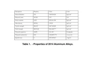
COUPLED THERMOMECHANICAL, THERMAL TRANSPORT AND SEGREGATION ANALYSIS OF ALUMINUM ALLOYS SOLIDIFYING ON UNEVEN SURFACES. Lijian Tan, Deep Samanta and Nicholas Zabaras Materials Process Design and Control Laboratory

E N D
COUPLED THERMOMECHANICAL, THERMAL TRANSPORT AND SEGREGATION ANALYSIS OF ALUMINUM ALLOYS SOLIDIFYING ON UNEVEN SURFACES Lijian Tan, Deep Samanta and Nicholas Zabaras Materials Process Design and Control Laboratory Sibley School of Mechanical and Aerospace Engineering188 Frank H. T. Rhodes Hall Cornell University Ithaca, NY 14853-3801 Email: zabaras@cornell.edu URL: http://mpdc.mae.cornell.edu/zabaras/
RESEARCH SPONSORS • DEPARTMENT OF ENERGY (DOE) • Industry partnerships for aluminum industry of the future • -Office of Industrial Technologies • ALUMINUM CORPORATION OF AMERICA (ALCOA) • Ingot and Solidification Platform • – Alcoa Technical Center • CORNELL THEORY CENTER
Brief introduction and motivation of the current study Numerical model to study deformation of solidifying alloys Closure criteria Computational strategies for solving the coupled numerical system Numerical examples: – preliminary studies of deformation of solidifying alloys –parametric investigations of solidification from molds with uneven mold topography (coupled thermal, solutal and momentum transport) Conclusions Future Work OUTLINE OF THE PRESENTATION
INTRODUCTION Surface defects in casting (Ref. ALCOA Corp.) (a) (b) (a) Sub-surface liquation and crack formation on top surface of a cast (b) Non-uniform front and undesirable growth with non-uniform shell thickness
INTRODUCTION • Aluminum industry relies on direct chill casting for aluminum ingots • Aluminum ingots are often characterized by defects in surface due to non-uniform heat extraction, improper contact at metal/mold interface, inverse segregation, air-gap formation and meniscus freezing etc • These surface defects are often removed by post casting process: such as scalping/milling • Post-processing leads to substantial increase of cost , waste of material and energy. • The purpose of this work is to reduce scalp-depth in castings • Detailed understanding of the highly coupled phenomenon in • the early stages of solidification is required
INTRODUCTION Engineered mold surface (Ref. ALCOA Corp.) • In industry, the mold surface is pre-machines to control heat extraction in directional solidification • This periodic groove surface topography allows multi-directional heat flow on the metal-mold interface • However, the wavelengths should be with the appropriate value to obtain anticipated benefits.
SHEMATIC OF THE PROBLEM DEFINITION • An Aluminum-copper alloy is solidified on an sinusoidal uneven surface. • With growth of solid shell, air – gaps form between the solid shell and mold due to imperfect contact – which further leads to variation in boundary conditions. • The solid shell undergoes plastic deformation and development of thermal and plastic strain occurs in the mushy zone also. • Inverse segregation caused by shrinkage driven flow causes variation in air – gap sizes, front unevenness and stresses developing in the casting.
SCHEMATIC OF THE HIGHLY COUPLED SYSTEM Mold Phase change andmushy zone evolution Heat transfer Solute transport Casting domain Fluid flow Deformation or mold non-deformable Heat transfer Contact pressure or air gap criterion Inelastic deformation • There are heat transfer and deformation in both mold and casting region interacting with the contact pressure or air gap size between mold and casting. • The solidification, solute transport, fluid flow will also play important roles.
PREVIOUS WORK • Zabaras and Richmond (1990,91) used a hypoelastic rate-dependent small deformation model to study the deformation of solidifying body • Rappaz (1999), Mo (2004) modeled the deformation in mushy zone with a volume averaing model: Continuum model for deformation of mushy zone in a solidifying alloy and development of a hot tearing criterion Rappaz (1999), Mo et al (2004). Surface segregation and air gap formation in DC cast Aluminum alloys – Mo et al. (1995-98) • Hector and Yigit (2000) did a semi-analytical studies of air gap nucleation during solidification of pure metals using a hypoelastic perturbation theory: Effect of strain rate relaxation on the stability of solid front growth morphology during solidification of pure metals – Hector and Barber (1994,95) • The inverse segregation and macro-segregation have also been studied by Chen, Heinrich, Samanta and Zabaras etc: Inverse segregation caused by shrinkage driven flows during solidification of alloys Chen et al. (1991 – 93), Heinrich et al. (1993,97) Effect of uneven surface topography on fluid flow and macrosegregation during solidification ofAl-Cu alloys – Samanta and Zabaras (2005) • Athermo-mechanicalstudy of the effects of mold topography on the solidification ofAl alloys • - Tan and Zabaras (2005)
SALIENT FEATURES OF OUR NUMERICAL MODEL • Volume averaging with a single domain and single set of transport equations for mass, momentum, energy and species transport • Individual phase boundaries are not explicitly tracked • Complex geometrical modeling of interfaces avoided • Single grid used with a single set of boundary conditions • A rate dependent hypo-elastic visco-plastic model is used for deformation of solid shell and mushy zone • Dynamic air gap – contact pressure coupling at the mold – metal interface • On the whole, a highly coupled model combining solidification and deformation in the • casting is used.
GOVERNING TRANSPORT EQUATIONS FOR SOLIDIFICATION (Ref :Shyll and Udaykumar, 1996) (Ref: C. Beckermann et al., explicit modeling of Interfacial terms) (Ref: Incropera, 1987-2000 mixture theory) Initial conditions : Isotropic permeability :
CLOSURE RELATIONSHIPS FOR FINDING CONCENTRATION AND FRACTION Lever Rule : (Infinite back-diffusion) T Scheil Rule : (Zero back-diffusion) C Cl (assumed constant for all problems)
MODELING DEFORMATION IN MUSHY ZONE • Low solid fractions usually accompanied • by melt feeding and no deformation due to • weak or non – existent dendrites • leads to zero thermal strain. • With increase in solid fraction, there is an increase in strength and bonding ability of • dendrites to non – zero thermal strain. • The presence of a critical solid volume fraction is observed in experiment and varies for different alloys. The parameter wis defined as: • Liquid or low solid fraction mush • -any deformation induced by thermal expansion is permanent. (Without any strength) • Solid or high solid fraction mush • -plastic deformation is developed only gradually.
MODEL FOR DEFORMATION OF SOLIDIFYING ALLOY • For deformation, we assume the total strain can be decomposed into three parts: • elastic strain, thermal strain and plastic strain. • Elastic strain rate is related with stress rate through an hypo-elastic constitutive law • Plastic strain evolution satisfy this creep law with its parameters determined from experiments (Strangeland et al. (2004)). • The thermal strain evolution is determined from temperature decrease and shrinkage. Strain measure : Elastic strain Plastic strain Thermal strain
Parameters for simulation of deformation in mushy zone Critical solid fraction for different copper concentrations in aluminum-copper alloy Ref: Mo et al.(2004) Creep law for plastic deformation Ref. Strangeland et al. (2004) Strain-rate scaling factor Stress scaling factor Activation energy Creep law exponent Volumetric thermal expansion coefficient Mushy zone softening parameter Volumetric shrinkage coefficient
THERMAL RESISTANCE AT THE METAL-MOLD INTERFACE Contact resistance: • At the very early stages, the solid shell is in contact with the mold and the thermal • resistance between the shell and the mold is determined by the contact conditions • Before gap nucleation, the thermal resistance • is determined by pressure • After gap nucleation, the thermal resistance • is determined by the size of the gap Example: Aluminum-Ceramic Contact Heat transfer retarded due to gap formation • Uneven contact condition generates an uneven thermal stress development and may accelerates distortion or warping of the casting shell.
MOLD – METAL BOUNDARY CONDITIONS Consequently, heat flux at the mold – metal interface is a function of air gap size or contact pressure: = Air-gap size at the interface = Contact pressure at the interface • The actual air – gap sizes or contact pressure are determined from the contact sub problem. • This modeling of heat transfer mechanism due to imperfect contact very crucial for studying the non-uniform growth at early stages of solidification.
SOLUTION ALGORITHM AT EACH TIME STEP Convergence criteria based on gap sizes or contact pressure in iterations All fields known at time tn n = n +1 Check if convergence satisfied Advance the time to tn+1 Contact pressure or air gap obtained from Contact sub-problem Solve for displacement and stresses in the casting (Deformation problem) Solve for the temperature field (energy equation) Decoupled momentum solver Solve for velocity and pressure fields (momentum equation) Inner iteration loop Solve for the concentration field (solute equation) (Ref: Heinrich, et al.) Yes Is the error in liquid concentration and liquid mass fraction less than tolerance Solve for liquid concentration, mass fraction and density (Thermodynamic relations) Segregation model (Scheil rule) No
COMPUTATIONAL STRATEGY AND NUMERICAL TECHNIQUES • The thermal problem is solved in a region consisting of both mold and casting to account for non-linear (contact pressure/air gap dependent) boundary conditions at the mold – metal interface. • Deformation problem is solved in both casting and mold (if mold deformable) or only the casting (if mold rigid, for most of our numerical studies). • Solute and momentum transport equations is only solved in casting with multistep predictor – Corrector method for solute problems, and Newton-Raphson method for solving heat transfer, fluid flow and deformation problems. • Backward – Euler fully implicit method is utilized for time discretization to make the numerical scheme unconditionally stable. • The contact sub-problem is solved using augmentations (using the scheme introduced by Larsen in 2002). • All the matrix computations for individual problems are performed using the parallel iterative Krylov solvers based on the PETSc library.
SOLIDIFICATION OF Al ON UNEVEN SURFACES Hypoelastic model without plastic deformation (Hector et al. 2000) • Heat transfer in the mold, solid shell and melt. • Heat transfer causes deformation (thermal stress). • Gaps or contact pressure affect heat transfer. • Solidification after air-gap nucleation not modeled.
GAP NUCLEATION TIME: EFFECTS OF WAVELENGTH • At the very early stages of aluminum solidification, contact pressure between mold and solid shell will drop at the trough due to thermal stress development. When this contact pressure drops to zero, gap nucleation is assumed to take place. This study compares very well with Hector’s semi-analytical study. It shows that gap nucleation is faster for smaller wavelength, smaller liquid pressure and better heat conductivity of the mold. • . • For rigid mold (with an topography • amplitude=1 µm, wavelength=1-5 mm), under liquid pressure 8000 Pa, the gap nucleation time • is in the order of seconds. • Physical Conditions: • Liquid pressure P=8000 Pa • Thermal resistance at mold-shell interface R=10-5 m2oCsec J-1
GAP NUCLEATION TIME: EFFECTS OF MOLD CONDUCTIVITY • Mold conductivity affects gap nucleation time • The higher the conductivity, the quicker the gaps nucleate from the mold surface In this calculations, the deformation of the mold is neglected to illustrate the effects of mold conductivity. Physical conditions: Liquid pressure P=10000 Pa Mold thickness h=0.5 mm Thermal resistance at mold-shell interface R=10-5 m2oCsec J-1 Wavelength=2 mm
GAP NUCLEATION TIME: EFFECTS OF MOLD MATERIAL (deformable mold) • When the wavelength is relatively small, the evolution of the contact pressure at the trough is mainly affected by the conductivity of the mold, i.e. the deformation of the mold does not play a crucial role. Physical Conditions: Liquid pressure P=10000 Pa Mold thickness h=0.5 mm Thermal resistance at mold-shell interface R=10-5 m2oCsec J-1 Wavelength=10 mm, (20 mm, 30 mm in the next two slides)
GAP NUCLEATION TIME: EFFECTS OF MOLD MATERIAL (deformable mold) • When the wavelength increases, the Ptr-t line is about to show a turn-around pattern when pressure reaches zero. This is defined as the `critical wavelength’ in the analytical studies of L. Hector. From this figure, we can say that the critical wavelength is slightly above 20 mm. In Hector’s analytical study, the critical wavelength is 16.60 mm, for iron mold and 14.03 mm for lead mold under the same conditions.
GAP NUCLEATION TIME: EFFECTS OF MOLD MATERIAL(deformable mold) • Notice that when the wavelength is greater than the critical value, the pressure-time curve shows a turn- around pattern before the contact pressure reaches zero. • This implies that a large wavelength is preferred since the contact pressure won’t decrease to zero to generate gap nucleation. • But in practice, we can never get a such a smooth mold topography with amplitude 1 µm and wavelength 30 mm as in these examples. Gap nucleation occurs for most casting processes.
SOLIDIFICATION OF Al-Cu ALLOY ON UNEVEN SURFACES • Combined thermal, solutal and • momentum transport in casting. • Assume the mold is rigid. • Imperfect contact and air gap • formation at metal – mold interface Solidification problem We carried out a parametric analysis by change these four parameters 1) Wavelength of surfaces (λ) 2) Solute concentration (CCu) 3) Melt superheat (ΔTmelt) 4) Mold material (Cu, Fe and Pb) Heat Transfer (Mold is rigid and non-deformable) Deformation problem Both the domain sizes are on the mm scale
SOLIDIFICATION COUPLED WITH DEFORMATION AND AIR-GAP FORMATION Important parameters 1) Mold material - Cu 2) CCu = 8 wt.% 3) ΔTmelt = 0 oC Air gap is magnified 200 times. • Preferential formation of solid occurs at the crests and air gap formation occurs at the trough, which in turn causes re-melting. • Because of plastic deformation, the gap formed initially will gradually decrease. • As shown in the movies, a 1mm wavelength mold would lead to more uniform growth and less fluid flow.
TRANSIENT EVOLUTION OF IMPORTANT FIELDS (λ = 5 mm) • Temperature • Solute concentration • Equivalent stress • (d) Liquid mass fraction Important parameters 1) Mold material - Cu 2) CCu = 5 wt.% 3) ΔTmelt = 0 oC (b) (a) • We take into account solute transport and the densities of solid and liquid phases are assumed to be different. • Inverse segregation, caused by shrinkage driven flow, occurs at the casting bottom.This is observed in (b). (d) (c)
TRANSIENT EVOLUTION OF IMPORTANT FIELDS (λ = 3 mm) • Temperature • Solute concentration • Equivalent stress • (d) Liquid mass fraction (b) (a) • For smaller wavelengths, similar result is observed: (1) preferential formation of solid occurs at the crests (2) remelting at the trough due to the formation of air gap. • For wavelength 3mm, the solid shell unevenness decreases faster than the case of 5mm wavelength. (d) (c)
VARIATION OF AIR-GAP SIZES AND MAX. EQUIVALENT STRESS λ = 5 mm, CCu = 5 wt.%, mold material = Cu • Air-gap sizes increase with time • Increasing melt superheat leads to • some suppression of air gaps • Initially, stresses higher for lower superheat • At later times, the difference is small Increasing melt superheat leads to some suppression of air gaps and a smaller stress at beginning stages. At later times, the difference of equivalent stresses is however small.
EFFECT OF WAVELENGTH ON AIR-GAP SIZES AND MAX EQUIVALENT STRESS ΔTmelt = 0 oC, CCu = 5 wt.%, mold material = Cu • Max. equivalent stress σeqvariationwith λ • σeq first increases and then decreases • Initially, σeq is higher for greater λ • Later (t=100 ms), stressis lowest for • 5 mm wavelength. • Air-gap size variation with wavelength λ • Initially, air-gap sizes nearly same for • different λ • At later times, air-gap sizes increase • with increasing λ
VARIATION OF AIR-GAP SIZES AND MAX. EQUIVALENT STRESS ΔTmelt = 0 oC, λ = 5 mm, mold material = Cu Increase of solute concentration leads to increase in air-gap sizes, but its effect on stresses are small. • σeq first increases and then decreases • Variation of σeq with Cu concentration • is negligible after initial times • Air-gap sizes increase with time • Increasing Cu concentration leads to • increase in air-gap sizes
VARIATION OF AIR-GAP SIZES AND MAX. EQUIVALENT STRESS ΔTmelt = 0 oC, λ = 5 mm, CCu = 5 wt.% Gap nucleation and stress development are prominent for a mold of higher thermal conductivity like Cu. For Fe or Pb molds, heat removal is inhibited due to their lower thermal conductivity. This in turn inhibits air-gap formation and development of stresses.. • Air gap sizes higher for Cu molds than • Fe or Pb molds • Equivalent stress far lower for Cu molds • than Fe or Pb molds
EFFECT OF INVERSE SEGREGATION – AIR GAP SIZES (a) With inverse segregation (b) Without inverse segregation By comparing the result with modeling inverse segregation and without modeling inverse segregation, we can find that inverse segregation actually plays an important role in air-gap evolution. • Differences in air-gap sizes for different solute concentrations aremore pronounced in the presence of inverse segregation.
VARIATION OF EQUIVALENT STRESSES AND FRONT UNEVENNESS Time t = 100 ms • Value of front unevenness and maximum equivalent stress for various wavelengths • one cannot simultaneously reduce both stress and front unevenness • when the wavelength greater than 5mm, both unevenness and stress increase-> implies wavelength less than 5 mm is optimum • Equivalent stress at dendrite roots • The highest stress observed for 1.8% copper alloy suggest that aluminum copper alloy with 1.8% copper is most susceptible to hot tearing • Phenomenon is also observed experi-mentally Rappaz(99), Strangehold(04)
EFFECTS OF SURFACE ROUGHNESS AND MOLD COATINGS • Effect of uneven surface topography and non – uniform contact on • microstructure evolution. • Incorporating the effects of surface tension and surface coatings to study • solidification on microscale. • Studying the effects of surface roughness on solidification on microscale. • Optimal design of a mold surface topography to minimize surface • defects.
PRELIMINARY STUDY OF EFFECTS OF SURFACE TENSION • In the macro-scale, the liquid pressure exerted by the droplet can overcome surface tension and causes the molten Aluminum droplet to contact the bottom of the cavity. Materials Process Design and Control Laboratory
EFFECT OF SURFACE TENSION • However, in the microscale, a change of surface tension could drastically change the solidification speed at very early stages of solidification. • This suggests taking account of surface tension in our future study is very important. Materials Process Design and Control Laboratory
CURRENT AND FUTURE RESEARCH • Shell growth kinetics • uneven growth • distortion Metal/mold interaction Air gap formation (non uniform contact and shell remelting) Meniscus instability Varying stresses in solid Lap marks, ripples, cold shuts Interfacial heat transfer Inverse segregation Microstructure evolution Surface parameters and mold topography in transport processes Macrosegregation
CONCLUSIONS • Early stage solidification of Al-Cu alloys significantly affected by non – uniform boundary • conditions at the metal mold interface. • Variation in surface topography leads to variation in transport phenomena, air-gap sizes • and equivalent stresses in the solidifying alloy. • Air-gap nucleation and growth significantly affects heat transfer between metal and mold. • Distribution of solute primarily caused by shrinkage driven flows and leads to inverse • segregation at the casting bottom. • Presence of inverse segregation leads to an increase in gap sizes and front unevenness. • Effect of melt pressure on solidification beyond gap nucleation was found to be negligible. • Effects of surface topography more pronounced for a mold with higher thermal conductivity • Computation results suggests that aluminum copper alloy with 1.8% copper is most susceptible for hot tearing defects. An optimum mold wavelength should be less than 5mm. • Overall aim is to develop techniques to reduce surface defects in Al alloys by modifying • moldsurface topography.
RELEVANT PUBLICATIONS • D. Samanta and N. Zabaras, “A numerical study of macrosegregation in Aluminum alloys • solidifying on uneven surfaces”, in press in International Journal of Heat and • Mass Transfer. • L. Tan and N. Zabaras, “A thermomechanical study of the effects of mold topography on the • solidification of Aluminum alloys”, in press in Materials Science and Engineering: A. • D. Samanta and N. Zabaras, “A coupled thermomechanical, thermal transport and segregation • analysis of the solidification of Aluminum alloys on molds of uneven topographies ”, submitted • for publication in the Materials Science and Engineering: A. CONTACT INFORMATION http://mpdc.mae.cornell.edu/