Chapter 9 Error Detection and Correction
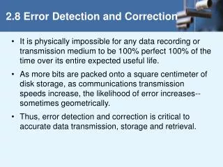
Chapter 9 Error Detection and Correction. Error Control Types of Errors Detection Correction. Error control. Data can be corrupted during transmission. For reliable communication, errors must be prevented, or detected and corrected. Source of errors. White Noise. Impulse Noise.

Chapter 9 Error Detection and Correction
E N D
Presentation Transcript
Chapter 9Error Detectionand Correction • Error Control • Types of Errors • Detection • Correction
Error control • Data can be corrupted during transmission. For reliable communication, errors must be prevented, or detected and corrected. Source of errors White Noise Impulse Noise Crosstalk Echo Jitter Attenuation Distortion
White Noise: Or thermal noise is an unwanted signal due to the heat created by the movement of electrons.But it is controllable. We can reduce its effect by using equipment. Impulse Noise: We never know when it comes. We can not predict it. i.e : spike noise is a scratch on a CD surface. Crosstalk: is the effect of one medium on another. It can be prevented by shielding the cables to protect the signals. Echo: We have echo when a sending devices some of the energy it has sent. Echo can be a problem if the devices and medium are not correctly designed. Echo can be prevented with good design and appropriate devices.
Jitter: is the result of a change in the signal when it passes through an electronic device. The device(such as amplifier) may create extra harmonics inn the signal. Jitter is not a problem if it is week. Attenuation: A signal may become too weak if it travels a long distance. Some of the energy of the signal may be transferred to heat to overcome the resistance of the medium. It can be prevented by repeater.
Figure 9-1 Errors Burst Singlebit
Figure 9-2 Single-bit error • In a single-bit error, only one bit in the data unit has changed.
Figure 9-3 Multiple-bit error
Figure 9-4 Burst error • a burst error means that two or more bits in the data unit have changed. • The number of bits affected depends on the data rate and duration of noise.
Figure 9-5 Redundancy • Error detection uses the concept of redundancy, which means adding extra bits for detecting errors at the destination.
Figure 9-7 VRC
Figure 9-8 LRC 11100111 11011101 00111001 10101001 11100111 11011101 00111001 10101001 LRC 10101010
Figure 9-9 VRC and LRC
Figure 9-10 CRC
Figure 9-11 Binary Division When the leftmost bit of the remainder is zero, we must use 0000 instead of the original divisor
Figure 9-12 Polynomial
Figure 9-13 Polynomial and Divisor
Figure 9-14 Standard Polynomials
Figure 9-15 Checksum
Figure 9-16 Data Unit and Checksum
Figure 9-17 Error Correction
Figure 9-18 Hamming Code
Hamming Code Figure 9-19
Hamming Code Figure 9-19-continued
Example of Hamming Code Figure 9-20
Figure 9-21 Single-bit error
Figure 9-22 Error Detection