Download
1 / 67
680 likes | 705 Views
Detailed analysis of Soyuz VHF-2 frequency characteristics & potential interference, ensuring safe communication & emergency preparedness for FAA users. Spectrum occupancy assessment, interference band testing, and antenna masking analysis overview.

E N D
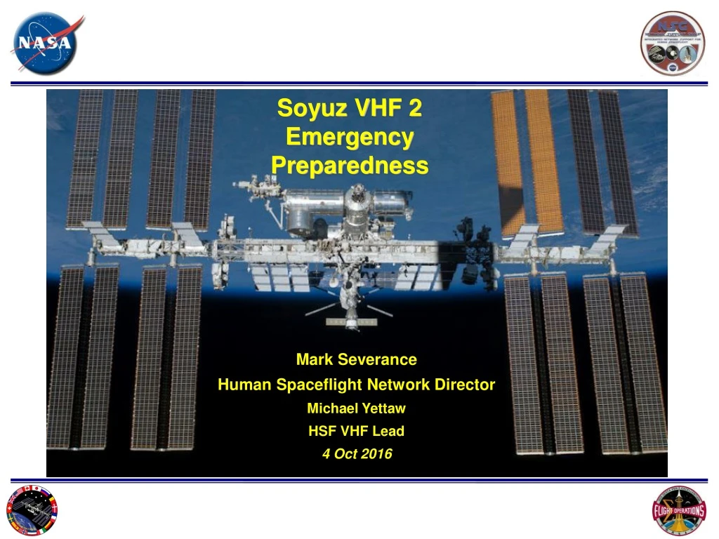
Mark Severance Human Spaceflight Network Director Michael Yettaw HSF VHF Lead 4 Oct 2016 Soyuz VHF 2 Emergency Preparedness
VHF2 Frequency Characteristics • Soyuz VHF 2 link characteristics • The Soyuz VHF 2 Downlink • Frequency is 121.750 MHz (FM analog modulation) • Extensive analysis has determined the Soyuz downlink is too weak to be received by aircraft or ground based receivers • The Soyuz VHF 2 Ground Uplink • Frequency is 130.167 MHz (FM analog modulation) • Uplink signals from the NASA ground stations can potentially interfere with aircraft on the adjacent frequencies, therefore mitigation is required. Photo – Soyuz launch 2
Downlink Interference AnalysisConclusions • The Soyuz downlink signal level does not exceed -126 dBm. This signal level is more than 19 dB below the typical squelch threshold of the typical AM receivers. • The Soyuz downlink signal cannot interfere with ground or airborne AM receivers The FAA concluded in October 2015 that the Soyuz VHF2 downlink will not cause harmful interference to FAA users. FAA supports annual emergency preparedness testing through operational coordination with affected users by VHF2 uplink from NASA Ground Stations. Photo – Soyuz Launch 3
Soyuz VHF2 Uplink Interference Analysis Photo – Milky way from from ISS 4
Soyuz Uplink Frequency band DataExcerpt from Final EV8-15-5018 VHF 2 spectrum Study 130.167 MHz ± 20 kHz The NTIA GMF database search for authorized users in the 130.147 MHz – 130.187 MHz failed to identify any users. This is a direct result of this portion of the spectrum being designated for non-Federal use only by the National Table of Frequency Allocations. The FCC ULS database was searched for licenses within the 130.147 MHz – 130.187 MHz frequency band. The search identified a total of 61 terrestrial-based licenses currently active within the CONUS. The search criteria was narrowed to identify authorized users within a 322 km radius of each potential NASA VHF-2 ground station, and the results identified eight licenses near AFRC (KHP9, KLF8, KLJ7, KLV5, KLX4, KRF6, WPE3, and WQET787), six licenses near WGS (KGQ7, WBQ9, WMV7, WQIZ981, WQL8, and WXE7), and two licenses near WSC ( KLY2 and WHP3). Each of the licenses identified are maintained by Aviation Spectrum Resources Incorporated (ASRI), and each license operates under an Aeronautical Enroute (FA) station class. The FA station class is defined as an aeronautical station which communicates with aircraft stations in flight status or with other aeronautical enroute stations. FA stations operating within this frequency band are used by aircraft operators to fulfill their requirements for Aeronautical Operational Control (AOC) communications which typically include dispatch, maintenance, scheduling, and other communications between the aircraft and the operating agency headquarters or others involved in the operation of a flight. These operations do not include Air Traffic Control (ATC) operations. Low Level Enroute communications, other than Terminal (In-Range), exist between an aircraft and its operating agency when the aircraft is at or above an altitude of 10,000 feet and below an altitude of 18,000 feet. Terminal (In-Range) communications consist of communications between an aircraft and the arrival or departure ground personnel (below 10,000 feet). In addition to the terrestrial-based FCC licenses, two other FCC licenses authorize the use of over 130 individual frequencies by aircraft operating over CONUS (KGF7 and KUF6). These licenses are maintained by Aviation Spectrum Resources Incorporated, and each license operates under an Aeronautical Enroute (Temporary) (FA2) station class. 1 2 1. Excerpt from Final EV8-15-5018, United States (US) Spectrum Occupancy Assessment and Sharing Study of the Soyuz Very-High Frequency-2 (VHF-2) Voice Communication System , Brian Rhodes, JSC Engineering, Technology, and Science Contract ES-0129-2311-00007, page 5 – 6 2. The FCC ULS Database Geosearch feature allows a maximum search radius criteria of 321.9 km 5
A test was conducted at Armstrong Flight Research Center (AFRC) to determine the potential interference bandwidth of the VHF 2 Ground Station 130.167 MHz uplink signal on typical AM receivers VHF 2 uplink induced receiver distortion was detected during testing when operating on frequencies from 130.1225 MHz to 130.225 MHz on a URC-200 test Receiver using an interference source of 130.167 MHz This yielded - 44.5 kHz to +55 kHz interference bandwidth Interference becomes apparent (> 10% distortion) if the VHF 2 Ground Station transmitter signal is within: 20 dB of the 130.175 MHz frequency. 5 dB of the 130.150 MHz frequency. Interference Test Summary results Photo – Nile from from ISS 6
Antenna Masking Analysis Antenna Gain Pattern - Azimuth Cross Section • Antenna masking as a means of interference mitigation was analyzed • Evaluation was performed on the antenna rear and sidelobes. 45 degree rear lobe is 25 dB lower than main beam Null is 45 dB lower than main beam 0 dB on scale = +18 dB 8
Uplink Interference Analysis NASA ground station uplink can be detected by terrestrial or aircraft AM receivers at all antenna pointing axes 9
Uplink Adjacent Frequency Interference Test Data Results Synopsis • VHF 2 uplink can be detected on frequencies from • 130.1225 MHz to 130.225 MHz • The gain pattern of the VHF 2 Ground Station antenna is approximately 25 to 45 dB lower than the peak gain at 90 degrees off boresight. This gain difference is insufficient for uplink interference mitigation. • Terrain blockage is not viable for 100% interference mitigation. • Interference mitigation is possible if uplink transmission occurs during non- flight periods of frequency license holders in the interference band. Photo – Texas at night from ISS 10
Soyuz VHF 2 Ground Station Interference Range Radius Study 11
The following data was used to determine the Soyuz VHF 2 uplink potential interference distance • Calculations were done with the following assumptions • As a general rule commercial aircraft descents occur over a longer distance than climb to altitudes • It is understood that aircraft Top of Descent distances vary • It is understood that Stepped Descents will add distance to a commercial airliner approach 12
Commercial Airliner Approach Distance Data was evaluatedto determine the scope of the interference window Photo – Sunrise over Western US from ISS 13
Typical Approach DistancesContinuous Descent Approaches shown • Recommended commercial Airliner approaches vary from 2.7 to 3.4 degrees 3 degree 126 mile Nominal Approach 35,000 ft. 126 miles CDA versus Stepped Descent Approach profiles 2.7 degree 140 mile Long Nominal Approach 35,000 ft. 2.7 Degree Approach 140 miles 1.75 degree 217 mile Maximum Expected Nominal Approach 35,000 ft. 1.75 Degree Approach 217 miles Table from: FAA-H-8083-15B figure 1-19, FAA Terminal Procedures Publication 14
Typical Approach DistancesDescent Profile Averages Distance to Touchdown (miles) 46 69 92 115 138 161 184 207 230 • Figure 1 taken from: Evaluation of Continuous Descent Approach as a Standard Terminal Airspace Operation. Joseph Post Office of Systems analysis, FAA_http://atmseminar.org/seminarContent/seminar9/papers/62-Cao-Final-Paper-4-4-11.pdf • Figure 1 taken from: Evaluation of Continuous Descent Approach as a Standard Terminal Airspace Operation. Joseph Post Office of Systems analysis, FAA_http://atmseminar.org/seminarContent/seminar9/papers/62-Cao-Final-Paper-4-4-11.pdf 15
Approach Distance Data Conclusions • Commercial Airliner Approach distance data conclusions • Typical commercial aircraft descent profiles vary from 70 mile to 220 miles • The majority of approaches occur within 100 miles Photo – Soyuz approaching the ISS 16
155 and 217 mile commercial Airliner approaches were evaluated to determine interference potential 17
155 Mile Aircraft Descent ProfileLong Nominal Approach 1,2 • This diagram will be used to evaluate NASA VHF 2 interference potential for Aircraft flying a 155 mile descent 1 Distance to Airport 62 miles 155 miles 93 miles 31 miles 125 miles 0 miles Boeing 737 Stepped Landing Approach Continuous Landing Approach 35,000 ft. 30,000 ft. Top of Descent 25,000 ft. 20,000 ft. Airport 15,000 ft. Notes: Altitude 10,000 ft. • 1. Typical Commercial aircraft descent profiles vary from 70 mile to 220 miles. The majority of approaches occur within 100 miles. Long range approach and landing profile displayed falls within outer range referenced in page 2 of Evaluation of Continuous Descent Approach as a Standard Terminal Airspace Operation. Joseph Post Office of Systems analysis FAA_http://atmseminar.org/seminarContent/seminar9/papers/62-Cao-Final-Paper-4-4-11.pdf Level Off 5,000 ft. 2 . Simplified drawing. Vertical Scale is exaggerated versus horizontal scale to enhance altitude resolution. 3. The terms Continuous Descent Approach (CDA) and Continuous Landing Approach are interchangeable 18
Interference Potential - Aircraft 155 Mile DescentWith Ground Station & 18,000 ft. Frequency Restriction OverlaysAirport at 155 Mile Distance From NASA VHF Ground Station • Interference potential window when Airport is 155 miles from NASA VHF ground station 18,000 foot (Altitude) Frequency License restriction 1 62 miles 155 miles 93 miles Distance to Airport 31 miles 125 miles 0 miles Boeing 737 Stepped Landing Approach Continuous Landing Approach 35,000 ft. 30,000 ft. Elevation Terrain Mask Top of Descent 25,000 ft. Smooth Earth 295 miles 199 miles 20,000 ft. 18,000 foot Altitude Line of Sight 0 15,000 ft. 93 miles 31 miles 62 miles 125 miles 248 miles 155 miles 186 miles 217 miles NASA VHF Ground Station 279 miles Altitude 10,000 ft. Level Off 5,000 ft. Distance From NASA Ground Station 1 . Simplified drawing. Vertical Scale is exaggerated versus horizontal scale to enhance altitude resolution. Airport 19
Interference Potential - Aircraft 155 Mile DescentAirport at 199 Mile Distance From NASA VHF Ground Station • Interference potential window size decreases when Airport is located 199 miles from NASA VHF ground station 18,000 foot (Altitude) Frequency License restriction Distance to Airport 62 miles 155 miles 93 miles 31 miles 125 miles 0 miles 1 Boeing 737 Stepped Landing Approach Continuous Landing Approach 35,000 ft. NASA VHF Ground Station 30,000 ft. Altitude Top of Descent Elevation Terrain Mask 25,000 ft. Smooth Earth 295 miles 199 miles 18,000 foot Altitude Line of Sight 20,000 ft. Airport 0 15,000 ft. 93 miles 125 miles 248 miles 155 miles 186 miles 217 miles 31 miles 62 miles 279 miles 10,000 ft. Level Off 5,000 ft. Distance From NASA Ground Station 1 . Simplified drawing. Vertical Scale is exaggerated versus horizontal scale to enhance altitude resolution. 20
Interference Potential - Aircraft 155 Mile DescentAirport at 248 Mile Distance From NASA VHF Ground Station • Interference potential window continues decreasing when Airport is located 248 miles from NASA VHF ground station 18,000 foot (Altitude) Frequency License restriction Distance to Airport 62 miles 155 miles 93 miles 31 miles 125 miles 0 miles 1 Boeing 737 Stepped Landing Approach Continuous Landing Approach 35,000 ft. 30,000 ft. NASA VHF Ground Station Top of Descent Elevation Terrain Mask 25,000 ft. Smooth Earth 295 miles 199 miles 18,000 foot Altitude Line of Sight 20,000 ft. Airport 0 15,000 ft. 93 miles 31 miles 62 miles 125 miles 248 miles 155 miles 186 miles 217 miles 279 miles Altitude 10,000 ft. Level Off 5,000 ft. Distance From NASA Ground Station 1 . Simplified drawing. Vertical Scale is exaggerated versus horizontal scale to enhance altitude resolution. 21
Interference Potential - Aircraft 155 Mile DescentAirport at 295 Mile Distance From NASA VHF Ground Station • Interference potential is mitigated by terrain masking when Airport is 295 miles from NASA VHF ground station 18,000 foot (Altitude) Frequency License restriction Distance to Airport 62 miles 155 miles 93 miles 31 miles 125 miles 0 miles 1 Boeing 737 Stepped Landing Approach Continuous Landing Approach 35,000 ft. NASA VHF Ground Station 30,000 ft. Top of Descent Elevation Terrain Mask Altitude 25,000 ft. Smooth Earth 199 miles 18,000 foot Altitude Line of Sight 295 miles 20,000 ft. Air port 93 miles 0 31 miles 62 miles 15,000 ft. 125 miles 248 miles 155 miles 186 miles 217 miles 279 miles 10,000 ft. Level Off 5,000 ft. Distance From NASA Ground Station 1 . Simplified drawing. Vertical Scale is exaggerated versus horizontal scale to enhance altitude resolution. 22
217 Mile Descent Profile 1, 2 • This diagram will be used to evaluate interference potential for Aircraft flying a 217 mile descent which is the outer range of nominal approaches 62 miles 217 miles 155 miles 93 miles 186 miles 31 miles 125 miles 0 miles Distance to Airport 35,000 ft. Top of Descent Boeing 737 Stepped Landing Approach Continuous Landing Approach 30,000 ft. 25,000 ft. 20,000 ft. Level Off Airport 15,000 ft. 10,000 ft. • Typical Commercial aircraft descent profiles vary from 70 mile to 220 miles. The majority of approaches occur within 100 miles. Long range approach and landing profile displayed falls within outer range referenced in page 2 of Evaluation of Continuous Descent Approach as a Standard Terminal Airspace Operation. Joseph Post Office of Systems analysis FAA_http://atmseminar.org/seminarContent/seminar9/papers/62-Cao-Final-Paper-4-4-11.pdf 5,000 ft. Altitude 2 . Simplified drawing. Vertical Scale is exaggerated versus horizontal scale to enhance altitude resolution. 23
Boeing 737 217 Mile Descentwith Ground Station & 18,000 ft. Frequency Restriction OverlaysAirport 217 miles from NASA VHF Ground Station • Interference potential window when Airport is 217 miles from NASA VHF ground station 18,000 foot (Altitude) Frequency License restriction 62 miles 217 miles 155 miles 93 miles 186 miles 31 miles 125 miles 0 miles Distance to Airport 35,000 ft. Top of Descent Boeing 737 Stepped Landing Approach Continuous Landing Approach 30,000 ft. 25,000 ft. Airport 20,000 ft. Level Off 199 miles NASA VHF Ground Station 350 miles 18,000 foot Altitude Line of Sight 15,000 ft. 0 31 miles 62 miles 93 miles 125 miles 341 miles 155 miles 186 miles 248 miles 310 miles 279 miles 217 miles 10,000 ft. Distance From NASA Ground Station 5,000 ft. Altitude 1 . Simplified drawing. Vertical Scale is exaggerated versus horizontal scale to enhance altitude resolution. 24
Boeing 737 217 Mile Descentwith Ground Station & 18,000 ft. Frequency Restriction OverlaysAirport 279 miles from NASA VHF Ground Station • Interference potential window size decreases when Airport is located 279 miles from NASA VHF ground station 18,000 foot (Altitude) Frequency License restriction 62 miles 217 miles 155 miles 93 miles 186 miles 31 miles 125 miles 0 miles Distance to Airport NASA VHF Ground Station 35,000 ft. Top of Descent Boeing 737 Stepped Landing Approach Continuous Landing Approach 30,000 ft. Altitude 25,000 ft. Airport 20,000 ft. 199 miles 350 miles 18,000 foot Altitude Line of Sight 15,000 ft. Level Off 0 31 miles 62 miles 93 miles 125 miles 341 miles 155 miles 186 miles 248 miles 310 miles 279 miles 217 miles 10,000 ft. Distance From NASA Ground Station 5,000 ft. 1 . Simplified drawing. Vertical Scale is exaggerated versus horizontal scale to enhance altitude resolution. 25
Boeing 737 217 Mile Descentwith Ground Station & 18,000 ft. Frequency Restriction OverlaysAirport 310 miles from NASA VHF Ground Station • Interference potential window continues decreasing when Airport is located 310 miles from NASA VHF ground station 18,000 foot (Altitude) Frequency License restriction 62 miles 217 miles 155 miles 93 miles 186 miles 31 miles 125 miles 0 miles Distance to Airport NASA VHF Ground Station 35,000 ft. Top of Descent Boeing 737 Stepped Landing Approach Continuous Landing Approach 30,000 ft. Altitude 25,000 ft. Airport 20,000 ft. 199 miles 350 miles 18,000 foot Altitude Line of Sight 15,000 ft. Level Off 0 31 miles 62 miles 93 miles 125 miles 341 miles 155 miles 186 miles 248 miles 310 miles 279 miles 217 miles 10,000 ft. Distance From NASA Ground Station 5,000 ft. 1 . Simplified drawing. Vertical Scale is exaggerated versus horizontal scale to enhance altitude resolution. 26
Boeing 737 217 Mile Descentwith Ground Station & 18,000 ft. Frequency Restriction OverlaysAirport 350 miles from NASA VHF Ground Station • Interference potential is mitigated by terrain masking when Airport is 350 miles from NASA VHF ground station 18,000 foot (Altitude) Frequency License restriction 62 miles 217 miles 155 miles 93 miles 186 miles 31 miles 125 miles 0 miles Distance to Airport NASA VHF Ground Station 35,000 ft. Top of Descent Boeing 737 Stepped Landing Approach Continuous Landing Approach 30,000 ft. Altitude 25,000 ft. Airport 20,000 ft. Level Off 199 miles 350 miles 18,000 foot Altitude Line of Sight 15,000 ft. 0 31 miles 62 miles 93 miles 125 miles 341 miles 155 miles 186 miles 248 miles 310 miles 279 miles 217 miles 10,000 ft. Distance From NASA Ground Station 5,000 ft. 1 . Simplified drawing. Vertical Scale is exaggerated versus horizontal scale to enhance altitude resolution. 27
Distance Calculations • The following pages list parameters for the three NASA VHF Ground Stations including : • 199 Mile 18,000 foot direct Line of Sight radius • 295 Mile nominal aircraft descent path radius • 350 Mile long approach descent path radius 28
NASA VHF Ground StationsLine of Sight Radius • The red circle for 199 miles radius for the three NASA Ground Stations is the Altitude Line of sight requirement for 18,000 feet • The aircraft frequencies in the V2 uplink frequency band are licensed for usage between 10,000 and 18,000 feet 29
Wallops VHF Ground Station Line of Sight Radius • The red circle for 199 miles radius around NASA Wallops VHF Ground Station (WGS) is the Altitude Line of sight requirement for 18,000 feet • The green circle for 296 radius miles is the affected distance of airports from WGS for landing approaches of less than 155 miles • The blue line for 350 miles radius is the affected distance of Airports from WGS for landing approaches of 217 miles or less • Altitude Line of sight requirement for 309 miles is 45,000 feet which is the maximum commercial passenger aircraft flying height 295 mile radius Wallops VHF Ground Station 199 mile radius 350 mile radius 30
White Sands Ground Station Line of Sight Radius • The red circle for 199 miles radius around NASA White Sands Complex VHF Ground Station (WSC) is the Altitude Line of sight requirement for 18,000 feet • The green circle for 296 radius miles is the affected distance of airports from WSC for landing approaches of less than 155 miles • The blue line for 350 miles radius is the affected distance of Airports from WSC for landing approaches of 217 miles or less 295 mile radius 199 mile radius White Sands Ground Station 350 mile radius 31
AFRC Ground Station Line of Sight Radius • The red circle for 199 miles radius around NASA Armstrong VHF Ground Station (AFRC) is the Altitude Line of sight requirement for 18,000 feet • The green circle for 296 radius miles is the affected distance of airports from AFRC for landing approaches of less than 155 miles • The blue line for 350 miles radius is the affected distance of Airports from AFRC for landing approaches of 217 miles or less 295 mile radius AFRC Ground Station 199 mile radius 350 mile radius 32
Frequency Licenses in the NASA Soyuz VHF 2 Uplink Band • The following pages contain the source lists and evaluation of frequency licenses in the NASA Soyuz VHF 2 uplink band Photo – Western US from ISS 33
The table to the right is a FCC ULS License search of users within 322 km (200 miles) of the VHF 2 Ground Stations in the 130.147 – 130.187 MHz Frequency band Users within 322 km of the NASA VHF Sites in the VHF2 Uplink Interference Band 1 The red shading indicates locations authorized for ground communications only which are out of line of sight to the NASA VHF Ground Stations 1. Excerpt from Final EV8-15-5018, United States (US) Spectrum Occupancy Assessment and Sharing Study of the Soyuz Very-High Frequency-2 (VHF-2) Voice Communication System , Brian Rhodes, JSC Engineering, Technology, and Science Contract ES-0129-2311-00007, page 7 34
Users within 350 miles of the NASA VHF Sites in the VHF 2 Uplink Interference Band • American Airlines Submitted the list (shown on the right) of additional users in the 130.1225 – 130.225 MHz frequency range The red strike through bars indicate users below the interference frequency range of 130.1225 to 130.225 The Grey strike through bar indicates Airport over 350 miles from the NASA VHF ground station 35
Service Level of Users within 350 miles of the NASA VHF Sites in the VHF 2 Uplink Interference Band • The NASA and American Airlines lists were combined and the service level of each license holder was added. The combined list is shown on the right. * * * The red strike through bars indicate ramp level users beyond Line of Sight to the NASA Ground Stations The purple strike through bars indicate fixed ground stations beyond Line of Sight to the NASA Ground Stations 36
NASA agrees with the American Airlines user data search with the following changes Users outside of 350 miles were deleted Users outside the interference band were eliminated Users with ramp level or fixed level licenses out of line of sight to the NASA VHF Ground Stations were eliminated There remain users near the VHF Ground stations that can potentially be affected by VHF 2 uplink transmission Interference would be mitigated by the predictable Soyuz 8 min pass length VHF 2 Uplink Band Usage Study Conclusion Photo – Soyuz rocket engines firing before landing 37
Frequency Licenses in the NASA Soyuz VHF 2 Uplink Band • The following page contains the combined list of frequency licenses in the NASA Soyuz VHF 2 uplink band for the following distances: • 199 Mile 18,000 foot direct Line of Sight radius • 295 Mile nominal aircraft descent path radius • 350 Mile long approach descent path radius Photo – Deep space from the ISS 38
The table to the right is the remaining list of license holders under 350 miles from the NASA VHF 2 Ground Stations Licenses within 350 miles in the VHF 2 Uplink Band * * NOTES: * An altitude of 18,000 foot altitude is required for line of sight at 199 miles. The listed frequencies are authorized for use between 10,000 and 18,000 feet. 1. From American Airlines provided frequency search list, 15 September 2016 2. From FCC ULS database search list in "Final EV8-15-5018", United States (US) Spectrum Occupancy Assessment and Sharing Study of the Soyuz Very-High Frequency-2 (VHF-2) Voice Communication System , Brian Rhodes, JSC Engineering, Technology, and Science Contract ES-0129-2311-00007, page 6 39
Conclusions 1 of 2 • 4 frequencies are affected: • 130.125 MHz, 130.150 MHz, 130.175 MHz, 130.120 MHz • 10 users are affected • Number of stations per user: • American Airlines – 18, ARINC – 4, British Airways – 1, Frontier Airlines – 1, Polar Air Cargo – 1, Long Island Jet Center – 2, Delta Airlines – 1, Shoreline Aviation Inc. – 1, Southwest – 2, Vee Neal Aviation Inc. - 1 Photo – Soyuz and Progress spacecraft docked to the nadir ports of the ISS 40
Conclusions 2 of 2 • International provision for emergency operation: ITU RR Article 4.9, "No provision of these Regulations prevents the use by a station in distress, or by a station providing assistance to it, of any means of radio communication at its disposal to attract attention, make known the condition and location of the station in distress, and obtain or provide assistance.“ • - NASA is currently working with the FAA on finalizing the notification procedure in the event of an actual spacecraft emergency. • October 2015 discussion concluded that the FAA Operational Center should be the official authority to issue the emergency order to the aeronautical community. Photo – two Soyuz spacecraft docked to the nadir ports of the ISS 41
Appendix Photo – long term earth exposure with lightning flashes 42
Frequency License Holder Enroute Service Level Assignment * NOTES: * An altitude of 18,000 foot altitude is required for line of sight at 199 miles. The listed frequencies are authorized for use between 10,000 and 18,000 feet. 1. From American Airlines provided frequency search list, 15 September 2016 2. From FCC ULS database search list in "Final EV8-15-5018", United States (US) Spectrum Occupancy Assessment and Sharing Study of the Soyuz Very-High Frequency-2 (VHF-2) Voice Communication System , Brian Rhodes, JSC Engineering, Technology, and Science Contract ES-0129-2311-00007, page 6 43 *
Background (1 of 2) • VHF2 frequency pair is the only space-to-ground voice channels between the Soyuz and capable ground stations. • The Soyuz will be used exclusively for ISS crew transport until at least 2018 • The Soyuz will continue to provide ISS crew transport until at least 2024 44
Background (2 of 2) • There are 6 Russian and 3 American ground stations capable of direct communication with the Soyuz spacecraft • The US Ground stations were deployed for emergency only support in 1997 • Nominal 4-orbit Soyuz mission between Kazakhstan and ISS has no visibility from CONUS. • If a nominal 34-orbit rendezvous is needed, VHF2 operation is not supported from CONUS stations. WGSGround Station AFRC Ground Station WSC Ground Station 45
Docked Soyuz/ISS Daily Orbit Ground Tracks Photo – Soyuz docked to the ISS 46
Why Changing the Soyuz VHF2 Frequencies Is not Feasible • Changing the Soyuz and uplink and downlink frequencies is not feasible for the following reasons: • The Soyuz comm system is hardwired on the current frequencies and does not have the capability for manual frequency changes by the crew or ground • Changes would be required not only all future Soyuz spacecraft but also to all 7 Russian ground stations which support Soyuz • Changes would also be required to the ISS as the Soyuz comm system is used for ship-to-ship communications during Soyuz approach/docking, undocking and departure. • The ISS VHF comm system is also hardwired fixed frequencies, without a manual frequency change capability • Implementing hardware changes across the Soyuz fleet, onboard ISS and across the Russian ground station network would involve multiple Russian organizations, some of which are outside of the NASA / Roscosmos ISS Partnership • While NASA could request such a change from our Russian partners, NASA would likely be requested to pay all change implementation costs (easily in the $M’s)
DFRC VHF 2 INTERFERENCE TESTING REV 4 Michael Yettaw Darren Mills 17 Nov 03 48
UPLINK INTERFERENCE CHARACTERIZATION TEST SETUP(LAB TEST) RCV TEST SIGNAL GENERATOR 130.150 MHz & 130.175 MHz V2 SIGNAL GENERATOR 130.167 MHz 50 OHM SPLITTER URC-200 VHF/UHF TRANSCEIVER (AIRCRAFT / GROUND STATION RECEIVER SIMULATOR 130.150 MHz & 130.175 MHz DISTORTION ANALYZER FIGURE 1 49
VHF 2 UPLINK INTERFERENCE CHARACTERIZATION TEST RESULTS • VHF 2 Interference induced Squelch break occurred on the 130.150 frequency at –80 dBm. • The signal level of the VHF 2 Ground Station antenna drops to a minimum of approximately 30 dB at 90 degrees off axis. • Interference is induced when the VHF 2 Ground Station uplink Transmitter signal strength rises to within 25 dB of the 130.175 and 15 dB of the 130.150 Frequency. • Interference can render the frequencies unusable(>10% distortion)if the VHF 2 Ground Station transmitter signal strength rises to within 20 dB of the 130.175 frequency and 5 dB of the 130.150 frequency . • Commercial aviation routes come within 15 miles of the VHF Ground Station exposing them to a signal level as high –34 dBm if directly in the antenna pattern. • VHF 2 induced receiver distortion was detected when operating on frequencies from 130.1225 to 130.225 on the URC test Receiver ( - 44.5 KHz to + 55 KHz interference bandwidth ). The test receiver 12.5 KHz tuning increments do not correspond to the actual receiver band reject capabilities. 50