Download

1 / 76
1.01k likes | 1.88k Views
PLGR DAGR. DEFENSE ADVANCED GPS RECEIVER (DAGR). REFERENCES. TO 31R4-2PSN13-8-1 TM 11-5820-1172-13. Purpose Characteristics / Capabilities and Features Component and Display Overview Battery Installation Powering on DAGR DAGR Setup & Modes of Operation Acquiring Current Position

E N D
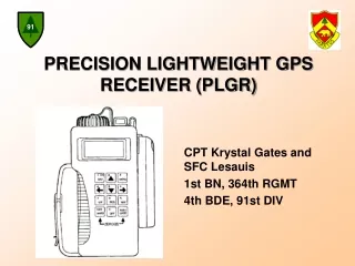
PLGR DAGR DEFENSE ADVANCED GPS RECEIVER(DAGR)
REFERENCES TO 31R4-2PSN13-8-1 TM 11-5820-1172-13
Purpose Characteristics / Capabilities and Features Component and Display Overview Battery Installation Powering on DAGR DAGR Setup & Modes of Operation Acquiring Current Position Waypoint Entry Navigation Zeroizing the DAGR Conclusion AGENDA
PURPOSE ENABLE THE USER TO OPERATE THE AN/PSN-13, DEFENSE ADVANCED GLOBAL POSITIONING SYSTEM RECEIVER TO FIND POSITIONAL DATA AND NAVIGATE FROM POINT TO POINT
Provides Position, Velocity, and Time (PVT) Includes battery pack and internal antenna with options for external primary power and antenna CHARACTERISTICS
All satellites in view are tracked using 11 channels Navigation using up to 10 channels L1: Coarse/Acquisition (C/A), Precise (P), and Encrypted P (Y) code capability L2: Precise (P), and Encrypted P (Y) code capability Accepts differential GPS signals Handheld or Host Platform mounted unit Signal acquisition using up to 12 channels Capabilities and Features
Backlit display and keypad for night operation Operates in all weather, day or night Produces no signals that can reveal your position Automatically tests itself during power up Can operate on +9 to +32 volts direct current (V DC) external power Can perform area navigation functions, storing up to 999 waypoints Stores up to 15 routes with up to 1000 legs for each route Capabilities and Features
Resists jamming Resists spoofing when crypto keys are installed Sealed against dust and water to a depth of 1 meter (3 feet) for 20 minutes Interconnects with other electronic systems Uses quick disconnect connectors and fasteners to allow easy unit replacement Compatible with night vision goggles (NVG) and does not cause blooming Uses internal compass to compute track and ground speed when moving at or below 0.5 meters per second. Capabilities and Features
Unpacking Packing Container Checking Unpacked Equipment Display Surfaces Keypad Connectors Inspect Equipment Check Equipment against packing List Check for modified equipment Repairs not covered by manual Unpacking DAGR
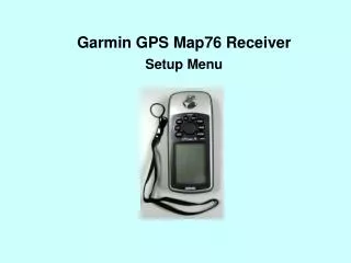
Location of Components • Integral Antenna • Display • J4 power connector • J3 external antenna connector • Keypad
J1 Serial Data I/O Port J2 Serial Data I/O Port Memory Battery and Cover Primary Battery Pack Location of Components
Lighting Status Indicator Primary Battery Status Indicator Function Key Labels (F1,F2,F3) Display Indicators
DAGR display contains three windows Only Fields in windows may be selected Display Windows
Display Windows Page Window • Majority of Display Interaction • May contain read only data or can be modified data • May contain multiple horizontal or vertical views
Tool Bar Window Three Display Regions Display Labels for function Keys Display Windows
Message Window Operator Notification Categorized as Notes Alerts Cautions Warnings Display Windows
Pop-up Window Displayed over Page Window Have Menus Allows Editing Help Text Display Windows
List Editors Text Editors Number Editors DAGR Editors
Keyboard Operation • Keypad is used to enter data • Keys have two labels • Function Keys
F1/In Function Key F2/Out Function Key F3/Status Function Key Keyboard Control
Keyboard Control • PWR/Quit Key • POS/page Key • Brightness/Menu Key • WP/Enter Function Key • Cursor Control Keys
Batteries Primary Battery and Memory Battery Types of Batteries Lithium AA 1.5 volt; Primary L-91; Battery Life 16.5 hours Alkaline AA 1.5 volt; Primary W-B-101; Battery Life 11.5 hours Alkaline AA 1.5 volt; Primary 714–4/5; Battery Life 7Hours Nickel Metal Hyride AA 1.5 volt; Primary; NH-15; Battery Life 10 Hours Lithium ½ AA 3.6 volt; Memory LS14500; Battery Life 8 Months Note Remove all batteries before storing DAGR Batteries
WARNING – Lithium batteries can explode Reverse polarity can cause damage to the battery and receiver CAUTION – Battery Types Do not mix battery type DAGR Used for 1st Time DAGR Resets to Default Note No Battery Charge Primary Battery Installation
a. Ensure power to the DAGR is off. Hold unit firmly upside down with the battery pack facing up. Push or pull latch located on the battery pack to release battery pack. Lift up on battery pack and remove from unit. Primary Battery Installation
e. If batteries are already installed, pull out on the battery removal strap to remove batteries from the battery pack. Dispose of batteries properly f. Position the battery removal strap into the channel of the battery pack before installing new batteries. g. Install new batteries and ensure correct polarity installation for each battery (marked on battery pack). h. Prior to installing the battery pack, inspect the battery pack gasket for damage or dirt. Lubricate or replace gasket if necessary. Ensure battery removal strap is not protruding from the battery pack. I. i. To install new battery pack, position tab on battery pack in slot on the DAGR. j. Close battery pack against DAGR until battery pack is engaged. Primary Battery Installation
Warning Lithium batteries can explode Reverse polarity can cause damage to the battery and receiver Caution DAGR Used for Time DAGR Resets to Default Note Battery Types Memory Battery Installation
a. Ensure power to the DAGR is off. b. Place unit upside down on non-abrasive surface with the memory battery cover facing up. c. Use flat blade screw driver to loosen three captive screws securing memory battery cover, then remove cover from unit. d. Remove the memory battery and properly dispose of battery. e. Prior to installing the memory battery cover, inspect the memory battery cover gasket for damage or dirt. Lubricate or replace gasket if necessary. e. Prior to installing the memory battery cover, inspect the memory battery cover gasket for damage or dirt. Lubricate or replace gasket if necessary. f. Install the memory battery. g. Install memory battery cover and tighten three screws. Memory Battery Installation
a. Push the (PWR/QUIT) key to turn the DAGR on. b. The power-on status message shows for two seconds, then time out if the following are true. • Self-test has passed • DAGR does not need initialization If not, push the (WP/ENTER) key to acknowledge. Powering on the DAGR
c. If a CV key, GUV key, or SV code condition exists, acknowledge messages accordingly. d. DAGR displays the SV Sky View page, then automatically switches to the Present Position page when current position is acquired. e. If keypad/display lighting is required, toggle lighting on and off by pushing and holding the (Bright/Menu) key. f. Adjust keypad/display brightness level by simultaneously pushing and holding the (Bright/Menu) key and using the (up/ down arrow) keys Powering on the DAGR
• Continuous - Tracks satellites to produce a continuous PVT solution, and uses the most power. • Fix - Tracks satellites to produce a current PVT solution, then automatically transitions to Standby mode after a position fix is obtained. • Standby - Operates at reduced power and does not acquire and track satellites, but performs all functions that do not require satellites. • Other available modes - Average, Time Only, Rehearsal, Test, and Off. Mode of Operation
Select Operating Mode Perform the following procedure to select the operating mode a. From any display except a message pop-up, push and hold the key until the Present Position page is displayed. b. Push the key. c. Highlight Select Op Mode, then push the key. d. Highlights the desired operating mode, then push the key.
Select Operating Mode(Continued) Display returns to the Present Position page displaying the selected operation mode.
Receiver Setup(MANUAL INITIALIZATION) If the DAGR has been moved between two different geographical locations and is not performing correctly, the DAGR may need to be initialized according to the DAGRs current location. The following procedure describes how to initially set up the DAGR Present Position page fields and edit field content when: • DAGR is having difficulty obtaining a position fix. • Datum is mismatched with navigation waypoints. • Datum does not match the geographical map used.
Receiver Setup(Manual Initialization) a. Power the DAGR on. b. Push and hold the key to access the Present Position page.
Receiver Setup(Manual Initialization) c. Select Datum (1) From the Present Position page, push the key. (2) Highlight Select Datum, then push the key (3) Scroll using the and keys to the geographical map being used, then push the key. (4) Display returns to Present Position page with datum change made.
Receiver Setup(Manual Initialization) d. Select Coordinate/ Grid system (1) From the Present Position page, push the key. (2) Highlight Select Coord/ Grid , then push the Key (3) Scroll using the and keys to select the Coord/ Grid system to the geographical map being used, then push the key. (4) Display returns to Present Position page with Coord/ Grid system change made.
Receiver Setup(Manual Initialization) e. Select units of measure or references (as required) (1) From the Present Position page, push the key, then highlight the Elevation field, then push the key. (2) Highlights Select Elev Units, then push the key. (3) Choose the appropriate unit of measure, then push the key. (4) Display returns to Present Position page with change made. (5) Edit Ground Speed and Track fields in similar manner f. Configure initialization data (position, time, speed, and track).
Receiver Setup(Manual Initialization)NOTE: Entering data may not be necessary if current almanac is available (1) From the Present Position page, push the key, then use the keys to scroll through and view fields as desired. If required, edit field content to configure initialization data for current geographical location. (2) When desired field is highlighted, push the key. An editor appears.
Receiver Setup(Manual Initialization) (3) For list editors, select the desired field content and push the key. For text or numeric editors, use keys and standard alphanumeric editor functions. Push the key to save numeric changes, or select SAVE when finished with text changes. (4) Display returns to the Present Position page with changes made to field content.
Receiver Setup(Manual Initialization) d. Select Coordinate/ Grid system From the Present Position page, push the key. Highlight Select OP Mode, then push the Key High light Continuous, then push the key. If a message is displayed instructing the operator that initialization is required, push the key.. Display returns to Present Position page with Coord/ Grid system change made.
Receiver Setup(Manual Initialization) h. Observe Present Position page. When attempting to acquire satellites after the signals have been blocked for a period of time (when exiting a building or cave), acquisition time may be improved by momentarily cycling the unit to STANDBY mode and then back to the previous operating mode. NOTICE!!!
Receiver Setup(Manual Initialization) • If Present Position page is not already displayed, push and hold the key until Present Position page is obtained. (2) The display position data fields stop blinking when the DAGR has obtained a current position fix. This current position data replaces any data entered manually. (3) DAGR is initialized with information corresponding to the current geographical location.
Receiver Setup(Manual initialization) i. Observe Sky View (SV) page. (1) If Present Position page is not already displayed, push and hold the key until Present Position page is obtained. (2) Repeatedly push the key until SV page is obtained. Satellite acquisition can be monitored from this page.
The DAGR obtains current position by simply turning the DAGR on with an open view of the sky. While acquiring satellites, DAGR displays the SV Sky View page. After satellites are acquired, DAGR automatically transitions to the Present Position page with current position coordinates shown. An indication of when the DAGR has obtained current position is provided by: Position data fields of the Present Position page remain solid black text and do not blink. On the SV Sky View page, solid black horizontal bars indicate satellites being tracked and data is collected; and Navigating shows at the top of the display. Acquire Current Position
Acquire Current Position The POS page set contains commonly used pages and are described in the upcoming slides: • Use the key or key to scroll pages.
Acquire Current Position PRESENT POSITION PAGE: Displays present position coordinates, coordinate and grid system, datum identifier, current operating mode, estimated horizontal error, figure of merit, elevation, elevation reference, ground speed, track, estimated time error, time figure of merit, time and date, MAGVAR, magnetic model year, and operator ID. Scroll the page vertically to view all field data.
Acquire Current Position Situational awareness Page NOTE: Range circles are shown on display when a vector map is loaded into the DAGR. Provides a geographical display of relationships between present position, track, waypoints, routes and alerts . Includes a North reference indicator, ground speed, track, position error data, and range scale.
Acquire Current Position Navigation pointer Page Displays a pointer directing the operator towards the display waypoint. Also displays current navigation method, destination waypoint number and name, azimuth, and range information.
Acquire Current Position IMAGE VIEWER PAGE: Displays, images or maps including current position (shown at center of display), landmarks, map objects, and selected waypoints. The operator uses zoom, pan, waypoint operations, and map selections to obtain desired view. The current position map is automatically displayed when loaded.