Download
1 / 17
170 likes | 213 Views
Learn about types of geometric corrections, how they are applied in remote sensing, and practical tips for accuracy. Explore systematic corrections, geo-referencing, orthorectification, projections, and resampling methods.

E N D
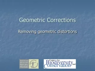
Geometric Corrections Removing geometric distortions
Why apply geometric corrections? • Co-register two or more images for multi-temporal change detection • Create or update image or thematic maps • Overlay other vector or raster georeferenced layers • Change the reference system or projection
Types of geometric corrections • Systematic corrections • Removes distortions from the sensor and movement of the satellite and earth • Geo-referencing • Uses ground control points (GCPs) to warp the image to a map • Orthorectification • Corrects for distortions caused by terrain by using a DEM • Often applied by modeling the sensor configuration • Projection or datum transformations • An automated process based on mathematical transformations
Systematic corrections • Scenes are rotated, aligned, and georeferenced to a user-defined map projection • Uses an automated process • Parameters required to do this are generated from sensor models and information recorded onboard the satellite • Position is determined from the satellite ephemeris data (position information) • Horizontal accuracy is ~50m or better from modern systems • Terrain distortions remain
Geo-referencing • Uses ground control points (GCPs) to warp the image • GCPs can come from another image, the field, or a map • Different warping methods are used • Affine • translation, rotation, scaling • Polynomial • 1st order (3 points) • 2nd order (6 points) • 3rd order (10 points) • Rubber sheeting • Local stretching to match control points • Not ideal for removing terrain corrections
Orthorectification • Transforms the image into an orthographic projection (each point as is viewed from above) • Uses a DEM to remove topographic distortions • Uses sensor models along with information about orientation and location of the sensor • Requires GCPs to georeference the image to a map base
Projections • Portraying the Earth’s curved surface on a flat surface • Distortions are unavoidable • Distance • Direction/Azimuthal • Scale • Area • Shape/Conformal • Local projections and datums • Universal Transverse Mercator (UTM) • Datum: World Geodetic System 1984 (WGS84) • National and regional projections • Geographic (Lat/Long) • European 1950 • Transforming between projections and datums is an automated process
Equidistant Cylindrical http://www.colorado.edu/geography/gcraft/notes/mapproj/mapproj_f.html
Equidistant Conical http://www.colorado.edu/geography/gcraft/notes/mapproj/mapproj_f.html
UTM UTM WGS84 Zone 36 http://www.colorado.edu/geography/gcraft/notes/datum/datum_f.html
Resampling • Different methods for determining pixel values after transformation • Nearest Neighbor – closest pixel • Bilinear Interpolation – 2x2 window • Cubic Convolution – 4x4 window • Nearest neighbor resampling necessary for categorical data http://www.malaysiagis.com/related_technologies/remote_sensing/article1.cfm
Practical information • It is difficult to use georeferencing methods to warp an image to fit an orthorectified image • Often a problem when using orthorectified Landsat data from the GLCF web site • Often better to use the non-orthorectified version of the image if it is available • Often difficult aligning two orthorectified image if different methods were used to create it • If relative (as opposed to absolute) accuracy is more important than use the same processing methods for both images if possible • RMS error estimates derived from the GCPs used to warp the image can give a false impression of the accuracy • When using a polynomial warp to georeference an image use the fewest number of points that give a reasonable fit. • Resampling degrades the data – keep it to a minimum