Download
1 / 15
150 likes | 172 Views
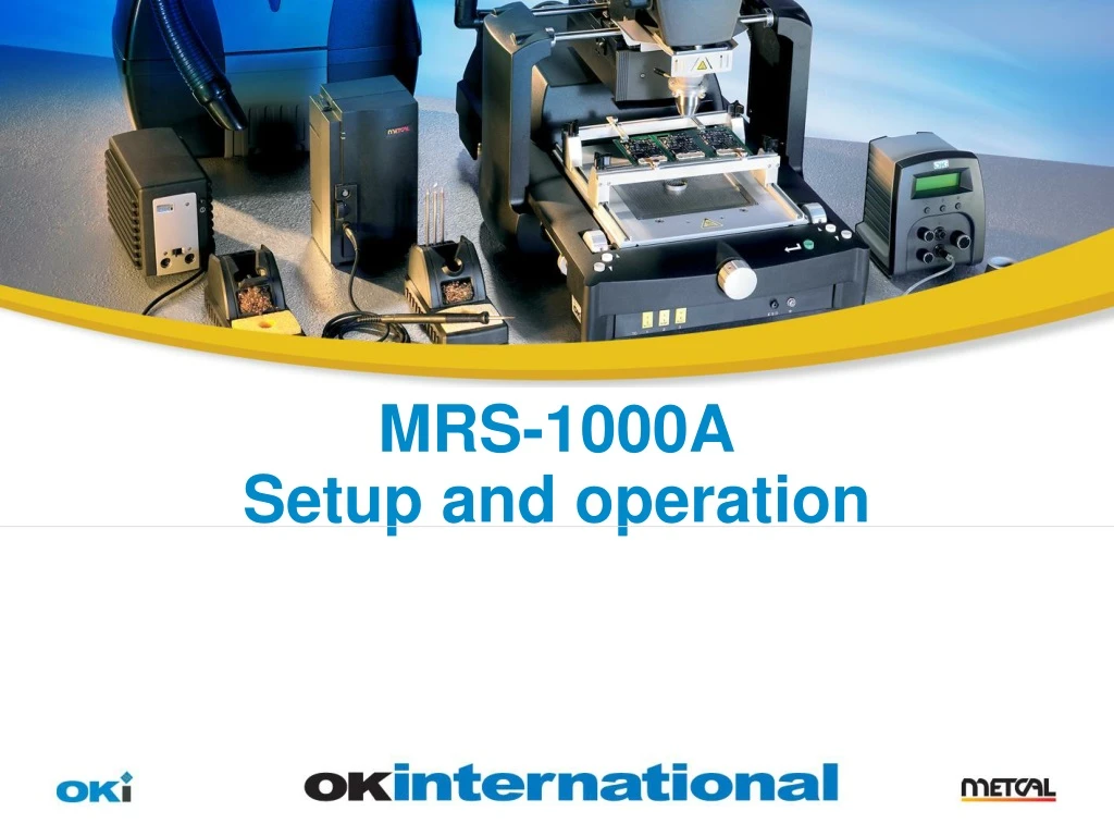
This guide provides step-by-step instructions for setting up and operating the MRS-1000A system. It explains initial assembly, board rail leveling, system modes, temperature settings, manual mode, run mode, and active setup.

E N D
MRS-1000A Setup and operation Usage Guidelines Throughout this template you will find tip-boxes to the left of the slides. To remove this box from the final presentation, simply click on the edge of the box (so that you select the whole box, not the text inside) and then press the delete key. Slide Description:Title Slide Usage:When creating a title slide, be sure to keep the title as short and descriptive as possible. The subtitle should be one sentence long.
Summary • The MRS-1000A and B are supplied with 4 main components PCT-1000 HCT-1000 ATH-1000A LM-1000 Plus the nozzle carrier. • There is a small amount of assembly required to connect all parts which will be explained in the following slides.
Initial assembly - PCT-1000 to ATH-1000* • A support bracket is required to be mounted to the ATH-1000* to the PCT-1000. • Remove the top plate of the PCT-1000 by unscrewing 4 x M3 screws. • Fix the bracket to this plate and the additional plate using 3 x M4 screws supplied. (The smaller mounting plate extends slightly from the main PCT plate) • Re attach the main plate to the PCT using 4 x M3 screws • Secure the back of the bracket to the PCT housing using 2 x M3 screws provided.
Initial assembly • Connector cable is provided with the HCT-1000. • LM-1000 must be secured to the ATH-1000 using screws provided
ATH-1000 and ATH-BH The co-planarity of the rails to the PCT can be adjusted using the adjustment screw located on the ATH-1000 After securing the ATH-BH to the ATH-1000*, lock the support rails using the grub screw supplied. Both screws can be adjusted using the driver supplied.
MRS – System set up • There are 4 available modes within the PCT and HCT units. • Setup • Manual • Run • Active setup • (Programming of the HCT is entered exactly the same as with the PCT-1000.) When the HCT-1000 and PCT-1000 are connected together, the HCT serves as the main controller . When this happens the time displays on the PCT are no longer shown.
Set up mode • Press the P once to change the program number, scroll to the correct number using + or - and re-press P • To enter set up mode, press and hold the “P” button for 2 seconds on the selected program. • In setup mode, the parameter which is being adjusted will flash repeatedly. • Using the + and – buttons adjust each parameter, then scroll to the next parameter using the P button. • When complete, hold the P to return to run mode.
Set up continued • Temperature settings on the HCT-1000 can be programmed from 25 to 450 degrees in 4 zones. • Zones 1 to 4 can be programmed from 1 second to 300 seconds. • TC: Can be selected to internal or external. Note: If external is set, the Thermocouple must be placed in the heat area. Failure to do this may result in damage to the heaters. TC1 is the master input for external monitoring. With the TC set to INT, the TC1 and TC2 can be used for reference. • Airflow levels can be adjusted in setup mode. • TM (Turbo mode) has been included for the Japanese market and should not be used in areas using 110v or 240v supplies.
Manual mode • In set up mode, each zone can be programmed to a maximum of 300 seconds. • When zone 1 is extended beyond this time, Manual mode is entered and all other zones are removed from the display. • Start and stop are triggered by the red button on the hand piece or red pedal on the dual foot switch.
Run mode To start a profile, the red button on the hand-piece or the HCT dual foot pedal should be activated. During the profile, the blue button can be pressed to toggle the function between remove and place. When the program is set to remove, the vacuum will activate and retract into the nozzle at the end of profile 4. The vacuum will continue for the duration of the Cooling zone. The profile can be aborted at any time during the cycle by pressing the red buttons. This will advance the profile to the Cooling zone.
Active set up • Within the active set up mode, it is possible to increase or decrease the temperature and time settings for each zone in real time. • To start the active setup. Press and hold the P until the first parameter flashes and begin the profile using the red button/footswitch. • Within each profile the + / - will adjust the temperature accordingly. • To shorten a zone and advance to the next profile, press the red button at the desired time. • To extend a zone length, Press and hold the P button within the last 5 seconds of its time and hold until the required time has been achieved. • The zone will advance to the next as you release the button and the new time will be stored into the program.
APR-MRS Demo KIT A new demo board has been released for the APR and MRS. The new board has been designed with a number of PBGA, CSP, micro SMD, PLCC, QFP, LGA, POP and discretes. The PCB includes component location lines to assist in demonstrating placement of BGA’s during Demo. Test points have also been included with pre-drilled holes so the board can be set up as a “gold” board for pairing of systems.
Calibration mode • Both the HCT-1000 and PCT-1000 have a revision of 1.5 which allows the TC inputs to be calibrated. • PLEASE NOTE! Calibration should only be performed AFTER the system has been run for at least to profiles. Calibrating the TC inputs when cold will offset the readings incorrectly. • To enter calibration mode, Press and hold the P then the on/off for 5 seconds and a calibration screen will appear. • Using a calibrated TC device as shown, use the +/- buttons to adjust the readings accordingly. • To return to normal settings, press P. • Details of this have not been included in the user manual so a separate document can be issued when requested.