Download
1 / 50
510 likes | 609 Views
Learn about transformation, scaling, sweeping, and topological operations in CAD systems to enhance design planning and execution. Explore mathematical tools such as matrices and affine transformations for precise modeling.

E N D
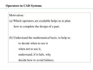
Operators in CAD Systems Motivation: (a) Which operators are available helps us to plan how to complete the design of a part. (b) Understand the mathematical basis, to help us to decide when to use it when not to use it, understand, if it fails, why decide how to avoid failures.
1. Transformations Use: (a) Building any 3D model (b) Viewing any 3D model Types of affine transformations of interest object transformations coordinate transformations
Affine transformations translations rotations Mathematical Tool: matrices Shape/size of an entities is invariant with respect to translation and rotation => We need only study translation, rotation of a point (vertex) x y z Vertex = Point, column vector: [ x, y, z]T =
Translation Coordinate transformation Object transformation Move r = [x, y, z]T by t = [tx, ty, tz]T : r’ = r + t, x = P in fixed frame oxyz x’ =P in frame o’x’y’z’ (translated w.r.t oxyz by –t): r’ = x’
Rotation Rotations in the XY plane Rotation of P by angle q about the oz : matrix A: Rot(z,q) Object transformation Rot(z, q) == Coordinate transformation by Rot( z, -q)
2.1. Scaling Use: to shrink / expand size of a part Uniform scaling: Multiply each coordinate in BREP by the scaling factor Operation: Map vertex, v( x, y, z) -> v’( sx, sy, sz) Property: Uniform scaling does not change the topology of the part
2.2. Non-uniform scaling Non-Uniform scaling scaling each coordinate, v( x, y, z) by different scaling factors, (sx, sy, sz) Transformed coordinates: v’(sxs, syy, szz). Question: Does the topology of the part change ? Applications of Non-uniform scaling: (a) Mold design from part (b) Clothing and Footwear design, …
Composition of Transformations Point in E3 as [x y z 1]T 4x4 matrices for transformations Translation Rot( X, q) Scaling
u q [x y z]T r’ O r [x’ y’ z’]T Rotation about an arbitrary axis u =[u1 u2 u3] = unit vector along given axis Rotation by angle q about u
Arbitrary rotation of Coordinate frame r = [x y z 1]T a point in OXYZ Oxyz = A new coordinate frame What are the coordinates of the point in Oxyz? (u1, u2, u3), (v1, v2, v3), (w1, w2, w3): DCs of u, v, w in OXYZ
Concatenation of Transformations Successive transformations: (i) Translate [-5 0 –5] (ii) Rotate(Y, 45) (iii) Translate [5√2 0 15]
Summary 1. affine transformations: preserve collinearity 2. Affine transformations useful in CAD 3. Matrices are useful to compute transformations 4. Translations, Rotations, Scaling 5. 4x4 matrices can represent all three of these 6. A series of transformation resultant transformation multiply corresponding matrix in reverse order
Operators in CAD: Boolean operators Boolean operations: U*, ∩*, -* inputs: regular 2-manifold solid(s) outputs: regular 2-manifold solid(s) Problem:
Operators in CAD: Sweeping Linear and Non-linear sweep Use: solid shapes from 2D sketches INPUTS: Profile (2D sketch, one or more loops) Sweep path (continuous, bounded curve) OUTPUT: regular 2-manifold solid
Operators in CAD: Sweeping.. Geometric Problem: all vertices, edges, faces of output easy to generate (i) fix sketch in frame OXYZ (ii) move OXYZ along sweep-path rotation determined by tangency, torsion A:= sweep outer loop B:= sweep inner loop(s) Out := A -* B
Operators in CAD: Sweeping... Other names: Extrude, Extrude-cut
Operators in CAD: Topological problems inSweeping (i)sweep path not smooth (C0, C1) (ii) self-intersection of the swept shape Example 1. How to generate shape? OR
Operators in CAD: Topological problems inSweeping.. Example 2. How to generate shape? Profile maintains orientation w.r.t. global frame Profile maintains orientation w.r.t. path FAILS!
Operators in CAD: Chamfer, Fillet Special cases of Blending INPUTS: Surfaces S1 and S2 that share an edge, E OUTPUT: Blending surface, B, between S1 and S2; E will vanish Interfaces between (B, S1), an (B, S2) are continuous chamfer: C0 fillet, round: C1
Operators in CAD: Chamfer Typical Uses: angled recess at the end of a hole angled edge to of shaft for ease of assembly
Operators in CAD: Chamfer computations (a) For each edge, create chamfer cross-section: a ‘triangle’ (b) sweep the section of each edge along the corresponding edge (c) fill ‘gaps’ at vertices (filler shapes) (d) Boolean (Part -* solid shape) for each solid shape and filler shape PROBLEM: what if neighboring faces are curved?
Operators in CAD: Chamfer… Geometry, Topological Problems step (a): cross-section step (c): filling “gaps” step (d) poor/changed topology
Operators in CAD: Fillet, Round Same as Chamfer, except: Geometric section used is Circular arc
Operators in CAD: Blending General case of Chamfers, Fillets and Rounds USES: Smooth the edge shared between two (spline) surfaces Merge two surfaces that are close, but not touching INPUTS: Two surfaces, and shared/blending edges Blend radius
Operators in CAD: Blending... Problems: 1. If edge is not C1, then sweep of blend arc is not C0 2. How to store the surface equation ? Blend computation: Rolling Ball Method
Operators in CAD: Tapers and drafts... Main Use: manufacturing related features: casting or molding INPUTS: (a) face / faces to be drafted (b) a neutral plane, that intersects the faces being drafted cross-section of the drafting faces on the neutral face unchanged (c) the draft angle OUTPUT: (a) Modified part geometry
Operators in CAD: Tapers and drafts... Examples (4th example is special!)
Operators in CAD: Tapers and drafts... Example 4: INPUTS: (a) Face(s) to be drafted (b) Draft line (c) Draft angle (d) Neutral plane
Operators in CAD: Tapers and drafts... Draft method: (i) Intersect the neutral plane with the draft faces, to get a series of edges (or a loop) that must stay fixed; (ii) Each point, p on the fixed loop belongs to a Draft face, F. (iii) For each point p, form the drafted edge: (a) P = plane through p, with normal = NF X NN (b) Intersect P with F to get drafting edge, ep. (c) Rotate ep by the drafting angle in plane P, to get the drafted edge
Operators in CAD: Tapers and drafts... This Draft method works for (some) non-planar draft-lines
10 20 Operators in CAD: Tapers and drafts... Draft failures (a) draft feature results in non-manifold geometry draft angle: 44 draft angle: 45 X X
Operators in CAD: Tapers and drafts... Draft failures (b) draft face intersection with neighboring face ill-defined Requires intersection after draft generation
ill-defined geometry Operators in CAD: Tapers and drafts... Draft failures (c) draft face intersection with neighboring face ill-defined NON-PLANAR
Operators in CAD: Surface operations: Offsets Inputs: Surface S, offset distance, r, offset direction Computation: for each point p on the base surface Normal = Np Offset point of p := p + r Np Planar surface: offset offset surface
Û offset p q surface offset z y a x Operators in CAD: Surface offsets, cylindrical surface q = a + xÛ (q - p).Û = 0 (a +xÛ – p).Û = 0 x = (p – a).Û Offset point: po = p + r (p - q)/|(p – q)|
pu pv Operators in CAD: Surface operations Surface offsets: BSpline surface Bspline Surface equation: p = p(u, v) Tangent vectors: Normal vector: For each point, p offset point po = p + rN NOT Bspline Offset surface equation: p(u, v) + r N(u, v)
Operators in CAD: Surface operations Find a grid of points on the surface, For each point of grid, offset point po = p + rN Fit a new BSpline surface through grid po BSpline offset is UNSTABLE ! poor geometry
Operators in CAD: Surface operations Surface offsets: Inputs: Surface S, offset distance, r, offset direction Computation: for each point p on the base surface Normal = Np Offset point of p := p + r Np Planar surface: offset offset surface
Operators in CAD: Offset -- interpretations non-intersecting faces extended intersecting faces trimmed non-intersecting faces extended
Operators in CAD: Trimming Trimming operation is based on intersection Trim R by B B R Trim B by R R must be EXTENDED
Operators in CAD: Trimming BSpline surface trimming Curve extension Intersection curve
Operators in CAD: Shelling Convert a solid to a “shell” Examples don’t shell left, front faces shell all don’t shell top, left faces don’t shell top face
Operators in CAD: Shelling Shell computation: For each face f, compute offset face, fo Intersect each pair of offset faces Re-compute BREP of solid [topologically difficult]
Operators in CAD: Lofting/ Skinning Use a series of (2D) “guide” profiles Put a “skin”: surface that interpolates each guide profile Example
Operators in CAD: Lofting/ Skinning Lofting computation: Complex, involving BSpline surfaces self intersection: fails Guide curves: possible improvement Instability: skinned surface not smooth
Issues in using CAD for PDM/PLM - Reuse same model (saves time/money) Parametric designs Design tables - Automated design verifications Design rules, triggers (constraints) Knowledge-based designs (using API’s)
Conclusions Understanding of CAD operations Using the correct operation to make a given shape Ability to anticipate & analyze why/when an opn may fail