Power Management for Memory Systems
ECE 692 Topic Presentation. Power Management for Memory Systems. Ming Chen Nov. 10 th , 2009. Why Power Control fo r M ain M emory ?. Memory capacities have been increasing significantly to accommodate CMPs. CPU is no longer the only major power consumer.

Power Management for Memory Systems
E N D
Presentation Transcript
ECE 692 Topic Presentation • Power Management for Memory Systems Ming Chen Nov. 10th, 2009
Why Power Control for Main Memory? • Memory capacities have been increasing significantly to accommodate CMPs. • CPU is no longer the only major power consumer. • Memory is highly under-utilized. • Requirement on amount • Requirement on bandwidth CPU & memory CPU : memory 1.21 85.4% 92.2% 0.69
Limiting the Power Consumption of • Main Memory Bruno Diniz, DorgivalGuedes, Wagner Meira Jr.Federa University of Minas Gerais, Brazil Ricardo Bianchini Rutgers University, USA Acknowledgments: The organization order and contents of some slides are based on Ricardo Bianchini’s slides.
Power Saving Vs. Power Control • A problem with two sides • Trade-off between power and performance • Power saving: • Guarantee performance first, then minimize power. • Performance is primary. • Save energy bill. • Power control: • Power capping: cooling, thermal, packaging, etc • Guarantee power budget first, then maximize performance. • Power budget is primary. • Avoid system failure and thermal violations.
What is This Paper About? • Bunches of work done to save power. • The first paper I have read on power control for memory. • Propose 4 policies for Power Limiting (PL) in memory. • Knapsack, LRU-Greedy, LRU-smooth, LRU-Ordered. • Combine Power Limiting with Energy Conserving (PL-EC). • Also provide performance guarantee. (PL-EC-Perf) An interesting paper that combines the two sides of the power problem together.
Power Actuators • RDRAM systems. • It is DRAM but not DDR SDRAM • Each chip can be transitioned independently. • Different power states
N S A S Power Limiting Memory Controller chip3 chip1 chip2 chip4
N S A S Power Limiting Memory Controller access chip3 chip1 chip2 chip4
N S A S Power Limiting Memory Controller chip3 chip1 chip2 chip4
Adjusting Power States Memory Controller N S S N chip3 chip1 chip2 chip4
Power Limiting Memory Controller access A S S N chip3 chip1 chip2 chip4 Different approaches to adjust states.
Knapsack: Key Idea • Multi-Choice Knapsack Problem (MCKP) • Object: memory device. • Choices: multiple (power) states. • weight : the power consumption. • cost : the transition overhead to the active state. • Goal: Minimize the cost with the constraint of weight by putting each object in a state. • MCKP is NP-hard, which is solved off-line.
Knapsack:An example power state chip # • LRU queue is maintained for active devices. • The LRU device is the victim. • Switch the power states of the two chips.
LRU-Greedy • An LRU queue for all devices • If a device is to be accessed, move it to the tail and: • Active? Go on … • Not active? • Put the LRU to the shallowest state. • Still not? adjust the state for the next device.
LRU-Smooth • A LRU queue for all devices • If a device is to be accessed, move it to the tail and: • Active? Go on … • Not active? • Put the LRU to the next lower-power state. • Still not? adjust the state for the next device.
LRU-Ordered: Key Idea • An LRU queue for active devices • An ordered queue for devices in low-power mode (shallowest first) • If a device is to be accessed: • Active? Move it to the tail of LRU and Go on … • Not active? • Move it from ordered queue to the tail of LRU queue. • Put the LRU to the top of the ordered queue. • Still not? adjust the state of the next device in the ordered queue to the next lower-power state.
Energy Conservation (PL-EC) • If idle time in the current state > break-even time, then lower power state. • Minimize delay*power2 by Knapsack for different # of devices in the active state. • Whenever the # of active states is going to change: • An active device is transitioned to the next low-power state when threshold expires. • A low-power device is transitioned to the active state and it does not violate the budget • The memory controller looks up the table and adjusts the states. • If the activating device violates the budget, the basic scheme (PL) is used.
Performance Guarantee (PL-EC-Perf) • To what extent the energy to be saved? • Basic strategy is from Xiaodong Li’s ASPLOS04 paper. • 5M-cycle epoch • User-defined slowdown (3%) compared with PL • Compute slack at runtime. • If slack < 0, disable EC until the end of epoch • Disabling EC means reverting back to the corresponding PL policy.
Evaluation Methodology • Single-core in-order CPU with integrated memory controller • Simics + memory subsystems • OS and physical mapping of virtual pages are both simulated. • Memory system is driven by traces generated by Simics. • Workloads: MediaBench, SPEC 2000, and client-server applications. • Memory size: 512 MB • Performance is measured by the execution time of a trace file.
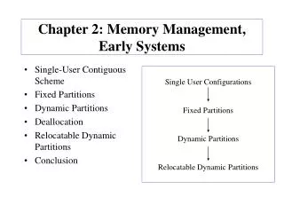
Performance Vs. PL Polices • 8 chips, 50% power budget. • Knapsack and LRU-Ordered are best.
Energy Vs. Policies • 8 chips, 50% power budget. • Compared with unrestricted execution. • Unrestricted < budget • bzip? (Critique)
Performance Vs. Budget • 8 chips under LRU-Ordered. • Performance degradation is very small.
Energy Vs. Power Budget • 8 chips, 50% power budget. • Saving decreases as budget decreases. • Uniform for all workload.
Performance for PL-EC-Perf • 8 chips, 25% power budget • LRU-Ordered • 3% slowdown • PD: an explicit energy saving algorithm • PL/PL-EC-Perf almost works no worse than PD • Exception is bzip2 ?
Energy Saving for PL/PL-EC-Perf • 8 chips, 25% power budget • LRU-Ordered • 3% slowdown • PD: an explicit energy saving algorithm • PL/PL-EC-Perf has more energy saving than PD. • PD tends to send some chips to very deep states.
Conclusions • Four power limiting policies are proposed.(PL) • Performance degradation is surprisingly low. • Limiting power + energy conserving (PL-EC) • Limiting power + energy conserving + performance guarantee (PL-EC-Perf) • Limiting power consumption is as effective as doing energy conservation explicitly.
A Performance-Conserving Approach for Reducing Peak Power Consumption in Server Systems Wes Felter, KarthickRajamani, Tom Keller IBM Austin Research Lab CosminRusu University of Pittsburgh Acknowledgments: The organization order and contents of some slides are based on Wes Felter’s slides.
Motivations • System designers can no longer afford to accommodate peak power of all components (over-provisioning) • System failures due to power overload and thermal violation. • CPU is no long the only major power consumer. • CPU and the main memory share the same power/cooling facility.
Anti-Correlation of Processor and Memory Power • Processor and memory are not simultaneously highly utilized in workloads. • Intuitively, the processor can’t keep itself and the memory busy
Unconstrained System Power In theory, the system can use 83W.
What is This Paper About? • Power shifting between processor and memory. • The first paper that proposes the concept of “power shifting”. • Power estimation model based on the # of activities. • Propose 3 policies for power control in the server level. • PLI, sliding window, and on-demand
Processor Power Model • Power Vs. Dispatched Instr./cycle • 100K-cycle interval • 28 applications • Linear regression
Memory Power Model • Power Vs. Bandwidth • 100K-cycle interval • 28 applications • Linear regression • Pmem=#ranks*#devices*VDRAM*((Iactive- Iidle)*BW/ PeakBW+ Iidle)+ Pothers
Power Actuators • Power consumption correlates strongly with activity. • Activity regulation techniques: • Instruction decoding throttling • Clock throttling: effective duty cycles • DVFS • For processor: • Throttle at the instruction dispatch unit of the pipeline. • For memory: • Limit the total # of memory requests
Memory Controller Memory Memory Request Counter Request Throttling System Architecture Processor Core Extensive clock gating Dispatched Insns. Counter Fetch Throttling Goes into powerdown mode when idle System Power Controller
Key Ideas • The # of activities is the same in the next interval. • Estimate the power based on history. • Allocate power based on estimates. • Power allocation is enforced by thresholds of the # of activities • Activity-dependent power and standby power
Proportional-Last-Interval Policy • Power estimation • CPU power = C1*DPC0+C2 • Memory power = M1*BW0+M2 • Power to be allocated: Pdynamic = Pbudget – C2 – M2 • DPC1 and BW1 for the next interval • Estimated active power: Pest = DPC0*C1+BW0*M1 • Power allocation • DPC1= DPC0*Pdynamic/Pest • BW1=BW0*Pdynamic/Pest • Threshold • Dth= DPC1*Period • Mth=BW1*Period
Other Related Policies • Sliding window • Shorter interval is better for estimation accuracy. • Larger interval is better for reducing noise. • A larger window includes 20 intervals. • On demand • No violations, no throttling • Interval should be small enough. • Run-To-Exhaustion (RTE) • Power is monitored cycle-by-cycle. • Throttle when power is violated. • Impractical but provides a comparison. • Static: proportional to the peak power
Simulation Environment • Traces from hardware (SPEC) and Mambo (e.g. JBB) • Integrated simulation environment • Turandot+PowerTimer (ZhigangHu et al., IBM TJ Watson) • Timing and power core model • 2GHz 970-like core w/ aggressive clock gating • 512KB L2 cache (power not simulated) • + MEMSIM • Timing and power DRAM model • 4GB, 4 ranks of 128-bit 400MHz DDR (PC3200) • Both simulators synchronized every cycle
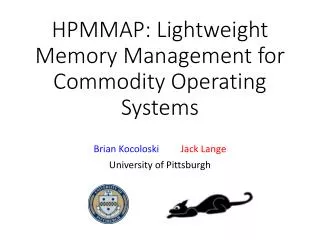
PLIVs. Static (1) • Budget: 40 W • Much better than static budgeting
PLIVs. Static (2) • Budget: 50 W • Average unconstrained power consumption < budget
Policy Comparison • 100K-cycle interval, 40W budget • On-demand is generally the best. • At the cost of at least one-interval budget violation
Normalized to RTE • On-demand and the sliding window are generally the best. • On-demand is even better than RTE for art. • Not proactively throttle activities and at cost of short violations.
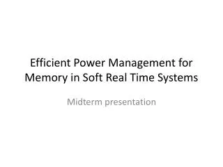
Interval Size (PLI) • ammp: highly variable even at small interval and steady power. • Small interval has better fit for variations. • Generally, highly application-dependent.
Critiques • Paper 1 • Lack explanations for different workload (e.g. bzip). • Examples used for policies are not typical. • Do not explain why the performance is surprisingly slightly degraded. • Paper 2 • Open-loop estimation based scheme • Model verification • Power is not shifting but throttled • Very large performance degradation even budget is larger than the average.