Download
1 / 32
400 likes | 597 Views
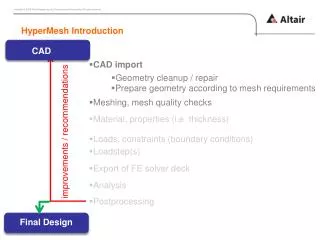
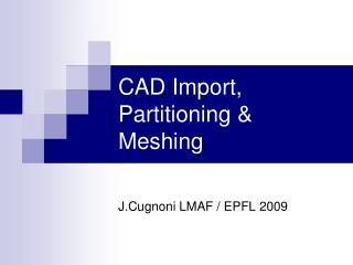
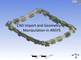
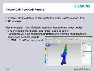
Learn about various translation methods and geometry cleanup processes to prepare geometry for meshing in CAD/CAE systems. Explore direct and standard exchange options, IGES import specifics, tolerant modeling techniques, file-direct importing details, and how to smooth/heal real geometry for improved accuracy.

E N D
Introduction • Several translation methods available to enable data exchange with CAD/CAE systems. • Translation can: • return incomplete, corrupt, or disconnected geometry • return geometry details unnecessary for CFD analysis • Geometry cleanup refers to processes required to prepare geometry for meshing. • Fix incomplete or corrupt geometry and connect disconnected geometry • Remove unnecessary details (defeaturing) • Decompose geometry into meshable sections • GAMBIT's virtual geometry operations and Semi-Automated Cleanup tools can help with the cleanup process.
CAD/CAE Data Exchange – Direct Translation • ACIS-based CAD/CAE programs (AutoCad, Cadkey, TurboCad) can export ACIS files (.sat or .sab) which can be imported into GAMBIT. • Parasolid-based CAD/CAE programs (Unigraphics, SolidWorks, PATRAN, ANSYS) can export Parasolid files (.x_t and .xmt_txt) which can be imported into GAMBIT. • CAD/CAE programs using proprietary geometry kernel • Direct (single-stage) Catia V4 or V5 .model file to ACIS translator • ADD-on (specific license key needed) • Contact your FLUENT account manager for pricing information
CAD/CAE Data Exchange – Standard Options • Standard Translation Options • Translation uses an intermediate, neutral or standard file format • Applicable for all CAD/CAE systems that can output: • STEP files (recommended) • IGES files • STEP (Standard for Exchange of Product model data) • International standard defining format for geometry and model information. • GAMBIT supports AP203 and AP214 • Preferred over IGES import. • Pro/E supports STEP export at no additional cost. • Other systems support STEP as add-on.
CAD/CAE Data Exchange – Standard Options • IGES (Initial Graphics Exchange Specification) • IGES can provide incomplete or disconnected geometry due to export issues with the CAD package. • Faces without volumes • Review summary of data before import to determine if there are any errors. • GAMBIT provides two options for IGES import • Spatial (Recommended) • All imported geometry comes in as real, supports solids • Native (Fluent) • Original IGES translator, does not support solids • Trimmed surfaces come in as virtual geometry. • Other options available during import for • Scaling the IGES file at import • Removing stand alone entities • Tolerant modeling and healing • Virtual cleanup of small edges and faces.
Import Mesh and Import CAD • Import Mesh and some Import CAD options result in faceted geometry. • Least preferred approach. • Options to create features using a Feature Angle. • STEP file and Direct import options available for Pro/Engineer. • Direct import accesses Pro/E kernel. • Requires add-on license. • File-direct options (native file readers) available for Parasolid and Pro/E files. • Requires add-on license.
File Direct Import • File-Direct import options for Pro/E and Parasolid files. • GAMBIT directly imports native files, such as Pro/E part files, eliminating geometry translation losses. • Option to bring in either solid model or the flow volume. • End faces of the flow volume should be created in original CAD package.
Tolerant Modeling • Every CAD system uses a minimum numerical precision (tolerance) for describing the geometry. • Coordinates of vertices/points, length of edges, size of faces, volumes. • The ACIS kernel in GAMBIT uses a high-precision tolerance of 10-6 (6 decimal places). • This precision may not be matched by the CAD/CAE software where the geometry was created. • Problems can arise upon import such as disconnected edges and faces. • Tolerant modeling is a technique which uses a variable or floating tolerance to connect geometry.
Tolerant Modeling • Available by activating the Make Tolerant option during CAD model import. • Also available after import inside the Heal Face (or Volume) Form. • Application • All Geometry files • Relatively large gaps • Real ACIS volumes generated during import. • Boolean operations subsequently possible • Adding/Subtracting additional geometry • Volume Extraction • Retaining only ½ or ¼ of model • Volume decomposition for better meshing
Smooth/Heal Real Geometry • Geometry imported from other CAD systems can lack the required accuracy and precision to render valid or connected ACIS geometry. • This results from numerical limitations in original CAD system, neutral file formats, or differences in tolerances between CAD systems and ACIS. • Use the check command to verify integrity of geometry/topology. • Check the connectivity of geometry using connectivity-based color coding. • Smoothing and Healing of Real geometry can help. • Smoothing is used to remove discontinuities in geometry. • Healing is used to detect and correct inaccuracies in model geometry due to different tolerances and translator limitations. • Available in the Smooth/Heal forms or as an option during CAD Import.
Smoothing and Healing Options • Smooth Options: • Replace Bad Geometry: Removes discontinuities or “kinks” in geometry. • Reduce Complexity: Simplifies the spline representation of geometry by reducing the number of control points. • Healing options: • Simplify Geometry: Converts spline geometry to analytic geometry, whenever possible. • Stitch Faces: Stitch together faces being healed to form one or more volumes. • Repair Geometry: Changes the definition of the edges and faces of geometry so that the model “fits together” well, especially at boundaries. • A tolerance is specified for some operations • The maximum distance between old and new geometry. • The maximum size of the gap between faces for Stitch faces. • Auto: Automatically calculates the tolerance based on the size of the geometry being smoothed/healed. • Manual: User can set tolerance (10-3 by default).
Face smoothing Smoothing and Healing Examples Healing Faces Stitch faces options Stitch faces, Repair geometry options
Geometry Cleanup Operations • Geometry cleanup is a follow on step, after using Tolerant modeling, Healing and Smoothing, to connect and de-feature geometry, and other problems. • Bridging gaps between edges/faces, small edges and faces, removing sharp angles, duplicate geometry etc. • Virtual geometry operations are used to perform geometry cleanup on edges and faces. • Merge, Connect, Collapse, Create from Wireframe etc.. • The cleanup operations can be conducted manually or using semi-automated tools. • Manual: Select the geometry for cleanup manually and then use virtual operations. • Semi-automated: Use specialized cleanup tools to automatically find problem geometry for cleanup and then use recommended real/virtual operations.
Virtual Geometry • Virtual geometry is “overlay” geometry that is defined based on underlying “host” geometry, which may be real or virtual. • Virtual geometry is named and colored differently than real geometry. • v_vertex, v_edge, v_faceandv_volume. • Meshing and boundary assignment operations are unaffected by virtual geometry. • Virtual geometry operations are accessed using dedicated virtual operation panels or virtual option on a real geometry panel. • On performing a virtual operation, any higher/lower geometry that is connected also becomes virtual and the host geometry is hidden from view. • The host can be retrieved by deleting the resultant virtual geometry and deselecting the Lower Geometry option. Virtual Face after Merging Three Non-Coplanar Faces
Virtual Geometry Operations • The virtual operations available are: • Merge: Replaces two connected entities (edge/face/volume) with a single virtual entity. • Split: Partitions an individual entity (edge/face/volume) into two or more connected virtual entities. • Connect: Combines two individual unconnected entities (vertex/edge/face) into a single virtual entity. • Collapse: Splits a face and merges the resulting halves with two neighboring faces. • Simplify Faces: Removes dangling edges. • Convert: Converts virtual geometry to real by sampling points on a mesh. • Boundary Defined Virtual Face Unite: Unites two non-coplanar faces using locations selected on their boundaries. • Stitch Faces: Creates virtual volumes from a set of connected faces.
Edge Connect (Virtual) • Edge Connect • Also available in Vertex and Face • Virtual (Forced) • Pick two or more edges you want to connect • Virtual (Tolerance) • Every picked edge within the tolerance will be connected • 10 % of shortest edge is recommended (default) • The shortest edge is shown by clicking the Highlight Shortest Edge button • The shape of the connected edge is an interpolated ‘average’ of the picked edges. • Use Preserve first edge shape to force result toassume shape of first edge in pick list. • Preserve first vertex location is available for vertex connects.
Face merge Edge merge Edge/Face Merge • Virtual Edge/Face merge options • Virtual (Forced) • Create one single edge/face from all edges/faces • Virtual (Tolerance) • Merge all edges shorter than Max. Edge Length • Merge all entities of higher entity angle than Min. Angle • No input will merge all vertices connected to two edges only Two faces One virtual face One virtual face Max. edge = Min. angle = 135
Face split Virtual Split • Edges, Faces and Volumes can be split using other virtual entities. Options are: • Face (Virtual) • Edges (Virtual) • Vertices (Virtual) • Locations (Virtual) • Vertex locations can be adjusted after the split • Limitations (for both face and volume split) • Split through voids, protrusions and dangling faces will create incorrect geometry • Order of picking is important • First and last location on a face must be on its boundary One face (real or virtual) Two virtual faces
virtual volume split Pick locations on edges, in sequence, to define splitting face: Perform virtual volume split: 1 2 4 3 Volume Split (Virtual and Faceted) • Volumes can be split with • Volume (real) • Face (real) or Faces (virtual) • All edges of the face must be connected to the volume • Locations (virtual) connected face one volume 2 virtual volumes Adjust split by sliding the virtual vertices (In Vertex Operations menu): Note: This can also be done after meshing.
Virtual Connect • Virtual Connect is available for vertices, edges and faces as options in the respective Connect forms. • Virtual (Forced) – Pick two or more entities you want to connect. • Virtual (Tolerance) – Every picked entities within the specified tolerance will be connected. • 10% of shortest edge is default. • For edge connect, you can select preserve first edge shape to force result to assume shape of first edge in pick list. • Preserve first vertex is available for vertex connect. • T-Junctions option is available for edges/faces at an angle or having gaps/overlaps.
Edge Splits Virtual Edge/Face Connect with T-Junctions • For edges, the T-junctions option splits edges by vertices that exist within a specified tolerance of the edges and then connects the split entities. • Preserve first edge shape option avoids distortion of edge shape. • For faces, T-junctions helps overcome common geometry problems in imported models such as gaps, mismatches and overlaps. • Utilizes projections, splits, and connects to overcome problems. T-Junctions with Preserve first edge shape on Overlapping Faces connected by T-Junctions unconnected real edges/faces connected virtual edges/faces
Boundary Defined Virtual Face Unite • Virtual option for Unite Faces can handle gross overlaps and gaps between faces. • Important locations for the final shape must be picked by user. • Tolerance option • Limitations • Order of picking boundary points is important. • Gaps larger than the mesh size can create trouble during meshing • Cannot handle large distances between overlapping faces Example: Unite square face in z = 0 plane with circular face in z = 0.05 plane. Select 6 points (A through F) IMPORTANT: C and E must lie on circular arc to obtain correct shape F E D C B A
Virtual Geometry Operations • Convert - converts non-real entities to real • Applicable to vertices, edges, faces, and volumes. • Face conversions require that a surface mesh be present. • Edges are sampled and real spline (NURBS) curve generated. • Sampling controlled by the GAMBIT default Geometry.Edge.VIRTUAL_NUM_SAMPLING_POINTS • Volume conversions require that all lower topologies can be converted • Topology and any existing mesh are preserved. • Face Simplify • Removes dangling edges and hard points from a face. • Result is virtual face • The face with dangling edge can also be split. Dangling edges
Real Unite Merge Tolerance Connect Comparison of Face Unite, Merge, and Connect • Unite (real) • Faces must have matching tangents. • Unite (virtual) • Gaps or overlaps are allowed. • There is no edge unite command. • Merge • Operates on real or virtual geometry. • Result is always virtual. • Faces must share an edge but they need not be tangent • Connect • Operates on real or virtual geometry. • Result can be either real or virtual. • Replaces selected entities with a single entity.
Semi-Automated Cleanup Tools • Clean up on models containing a large number of faces can be tedious. • Cleanup Tools can semi-automate this process using virtual and real operations: • Finding the problem areas • Suggesting fixes • More information in the Semi-Automated Cleanup lecture.
Working with CAD Geometry: Procedure • Import CAD geometry. • First preference should be for native formats, then the standard formats. • STEP is usually better than IGES. • Preparing the model in CAD can smooth the cleanup process. • See Appendix for guidelines on CAD Interoperability for different packages. • Turn on Tolerant Modeling. • Delete all unnecessary geometry. • Check validity of imported geometry. • Correct invalid geometry (Smooth/Heal and/or reconstruct). • Check connectivity by color coding • Helps distinguish between connected and unconnected entities. • White and Orange colors indicates disconnected entities.
Working with CAD Geometry: Procedure • Connect Geometry (Manual or Semi-Automated Cleanup) • Real/Virtual connect of vertices, edges, and faces, in steps, based on increasing connect tolerance • Connect with T-Junction Option. • Use forced connect operation for entities out of tolerance • Defeature/Simplify Geometry (Manual and/or Semi-Automated Cleanup) • Merge small edges and faces with neighbors. • Merge faces at large angles. • Remove hard edges. • Remove sharp angles for better meshing. • Create additional geometry (if necessary) and form volume(s). • Some of this may need to be done before resorting to virtual geometry commands so that real Boolean operations are available. • Bridge real and existing virtual geometry together using virtual geometry. • In 3D, use face stitch command to create virtual volumes. • Decompose volume (if necessary) using virtual split operations. • Generate the mesh
General Guidelines for CATIA • Wherever possible use basic geometry and primitive solids for model creation. • Big extracted surface can be broken into smaller surfaces by using the Dissemble option. • If one or more bodies (volumes) in CATIA are sharing the same face then there will be duplicate faces upon import in GAMBIT. • Hide the sketches, extracted edges and boundaries before exporting file from CATIA; otherwise, these entities will appear as edges in GAMBIT. • For assemblies, confirm that all component files are in the same directory. • Use tools available in CATIA to validate geometry prior to export. • If using STEP, import the data back for a loop test to certain that the solid model data in STEP file can be recreated in CATIA.
General Guidelines for Pro/Engineer • For a better data exchange, it is recommended to create models in Pro/E with absolute accuracy from the beginning. • The setting enable_absolute_accuracy yes needs to be included in configuration file config.pro. • Delete all non-referenced geometry and external reference. Do not use any suppressed construction geometry (activate all layers). • For assemblies, confirm that all component files are in the same directory. • Components of an assembly should have names no longer than 16 characters. • Before export, use Info→Geom/Check to check for design problems. Indicated features are likely to cause problems in the target system. • If using neutral formats, import the data back for a loop test to certain that the solid model can be recreated in Pro/E.
General Guidelines for Unigraphics • Avoid modeling practices that creates unparameterized features. It will reduce corrupt solids and will facilitate repair of invalid geometry. • Wherever possible avoid using blend features in Unigraphics. • Use of tolerant modeling feature in Unigraphics should be avoided. • Use File→Utilities→Part Cleanup option to delete any empty groups and un-referenced objects from the part file. • Use Info→Analysis→Examine Geometry command to analyze the model and fix any errors prior to export. • For assemblies, confirm that all component files are in the same directory. • If using intermediate file, import the data back for a loop test to be certain that the solid model data in the file can be recreated in Unigraphics.
General Guidelines for SolidWorks/SolidEdge • Use a tighter tolerance (close to 10-6) in SolidWorks/SolidEdge. • Wherever possible use basic geometry and primitive solids for model creation. • Make all geometry visible and selectable. Remove unnecessary geometry, layers, annotation from the file(s). • Delete all non-referenced geometry and external reference. Do not use any suppressed construction geometry (activate all layers). • Solid models should be prefered over the wireframe. • For assemblies, confirm that all component files are in the same directory. • Use tools available in SolidWorks/SolidEdge to validate geometry prior to export. • If using intermediate formats, import the data back for a loop test to be certain that the solid model can be recreated in SolidWorks/SolidEdge.