Download
1 / 47
470 likes | 664 Views
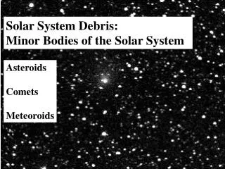
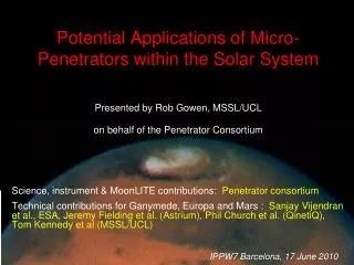
Potential Applications of Micro-Penetrators within the Solar System. Presented by Rob Gowen , MSSL/UCL on behalf of the Penetrator Consortium. Science, instrument & MoonLITE contributions: Penetrator consortium

E N D
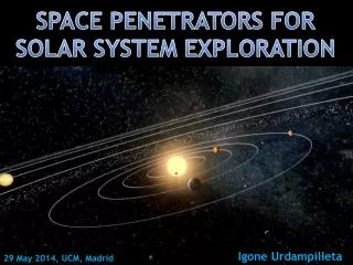
Potential Applications of Micro-Penetrators within the Solar System Presented by Rob Gowen, MSSL/UCL on behalf of the Penetrator Consortium Science, instrument & MoonLITE contributions: Penetrator consortium Technical contributions for Ganymede, Europa and Mars : Sanjay Vijendran et al., ESA, Jeremy Fielding et al. (Astrium), Phil Church et al. (QinetiQ), Tom Kennedy et al (MSSL/UCL) IPPW7 Barcelona, 17 June 2010
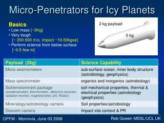
Kinetic Penetrators ? Spin-Down Descent Module release from Orbiter Cancel orbital velocity Reorient Penetrator Separation PD fly away prior to surface Impact • Low mass projectiles • High impact speed ~ up to 400 ms-1 • Very tough ~10-50kgee • Penetrate surface and imbed therein • Undertake science-based measurements • Transmit results Re-orient PDS separation from penetrator Operate from below surface Delivery sequence courtesy SSTL
Why penetrators ? Advantages: • Simpler architecture • Low mass • Low cost • Explore multiple sites • Natural redundancy • Direct contact with sub-regolith (drill, sampling) • Protected from environment (wind, radiation) Limitations: • Require a suitable impact surface • Low mass limits payload options • Impact survival limits payload options • Limited lifetime • Limited telemetry capacity
History: feasibility & heritage • No successful mission yet but ... • Lunar-A and DS2 space qualified • Military have been successfully firing instrumented projectiles for many years • Most scientific instruments have space heritage DS2 (Mars) NASA 1999 ? Mars96 (Russia) failed to leave Earth orbit Japanese Lunar-A cancelled Many paper studies and ground trials
Penetrator Science Capabilities A wide variety of candidate Instruments ...
Opportunities Status MoonLITE (UK) Postponed indefinitely following adverse UK funding situation. Pursuing other options Mass budget insufficient to include penetrators on JGO JGO (ESA) Penetrators currently being studied for inclusion on JEO JEO (NASA) Mars options being studied in current ESA contract Mars ?
MoonLITE Science & Exploration Objectives “The Origin and Evolution of Planetary Bodies” “Waterand its profound implications for life andexploration” “Ground truth & support for future human lunar missions”
Polar comms orbiter 3 MoonLITE Mission • Delivery and Comms Spacecraft(Orbiter). • Payload:4 penetrator descent probes • Landing sites:Globally spaced - far side - polar region(s) - one near an Apollo landing site for calibration • Duration:>1 year for seismic network. Far side 4 2 1
Pendine Impact Trial – May 2008 • Designed and built 3 full scale penetrators (~0.5m long, ~13kg mass) • Aluminium body • Segmented aluminium inner compartments • Fired into large sand target (~2m*2m*7m) (lunar regolith simulant) • One firing per day for 3 days. • All at 300m/s Inners Stack
Impact trial – internal architecture Mass spectrometer Radiation sensor Batteries Magnetometers Accelerometers Power Interconnection Processing Micro-seismometers Accelerometers, Thermometer Batteries,Data logger Drill assembly
Rocket sled Penetrator Impact Trial - Configuration
Pendine Trials Outcome All 3 impacts ~310m/s (nearly supersonic), ~8 nose up (worst case) Penetration depth ~3.9m Gee forces: ~ 5kgee along axis ~16kgee spikes Significant ablation to nose and underside No distortion to inner payload bays All 3 penetrators survived ✓
Where did this get us ? For Lunar case : • Demonstrate survivability of penetrator body, accelerometers, power, interconnect system, and instrument elements. • Determined internal acceleration environment at different positions within penetrator. • Extended predictive modelling to new penetrator materials, and impact materials. • Assessed alternative packing methods. • Demonstrated elements would fit into a penetrator of this size
Ganymede • Ganymede was prime focus of ESA ‘Jovian Moons’ penetrator study.(special provision for UK) • Started ~Nov 2009, and ends next month (July 2010) • Astrium Prime (Delivery System), MSSL (Penetrator), QinetiQ (impact survival, comms), UCL (impact sites and materials) • Objectives: • define delivery system and penetrator for potential inclusion in EJSM ESA JGO spacecraft. • determine mass and feasibility • Study requirements: • operational lifetime 2 planetary body orbits • assess battery only solution • total system mass <= 100kg • high TRL, feasible
Ganymede – General Characteristics • Icy body (~70-150K) • Habitable subsurface ocean ? Thick crust several 100’s km. not suitable for ground penetrating radar–much more suited to in-situ, seismometer, magnetometer detection and characterisation
Ganymede – Impact Characteristics • Surface Materials • Bright: believe water ice • Dark: spectrally consistent with hydrated silicates(need in-situ measurements to confirm chemistry) • Varied Terrains • ridges, cracks, bands • many craters • Impact surface conditions • Old heavily cratered surface (Byrs) with potentially substantial regolith. • Slopes in region 0-20 UrukSulcus and 0-30 for Galileo Regio at large scales*. Portion of Galileo Regio (old dark terrain) Note smoother area on right ridges band 25km *Giese et.al.[1998], Oberst et.al.[1999]
Ganymede Penetrator Payload Model payload of 6 instruments selected for study. • Micro-seismometer (seismic activity levels, internal body structure including subsurface ocean characterisation) • Magnetometer (internal ocean and currents, intrinsic and induced fields) • Microphone (acoustic frequencies to listen ice cracking rates and strengths) • Thermal Sensor (engineering use, subsurface temperature & temporal variations) • Accelerometer (engineering use, surface hardness and layering) • Descent camera (PDS mounted, geological context) (avoided instruments which require external access due to perceived low TRL of this technology)
Ganymede Penetrator Design Ganymede Penetrator design Length : ~34cmDiameter: ~15cm Length : ~55cmDiameter: ~16cm Lunar Penetrator design • Harder ice impact material (→ steel shell) • Fatter body for shallower penetration (→ less signal attenuation, improved aerial area) • Shallower penetration (→ less need for tail) • Rear release stud (→ for connection to PDS)
Impact Modelling (QinetiQ) • Baseline impact material for simulation selected as polycrystalline ice at -10C with 10 Mpa compressive strength.(adaption for cryogenic ice to be performed) • Simulations up to 40 Mpa show that steel shell can survive 300m/s impact. • Penetration depth range ~0.5 to 1m depending on impact material strength. QinetiQ 40 Mpa ice Penetration depth ~0.5m
Detailed Design (MSSL/UCL) • Battery only solution can provide 2 week lifetime with vacuum flask concept
Communications (QinetiQ) • Rear mounted non-conductive coupling • UHF based, high TRL • Conservative signal attenuation assessed • High latitude site (e.g. ~75) for best data volume return QinetiQ
Delivery System (Astrium) • Bipropellant delivery system solution • Achieve impact velocity, orientation (incident and attack angles) • Orbiter visible throughout descent • Fly away before impact Astrium Ltd.
Ganymede Penetrator Resources • Mass for JGO: (including maturity and system margins) • Penetrator ~15.4kg • PDS Mass ~70kg • Total PDM mass therefore ~85kg • Penetrator: (2 weeks operational lifetime) • Power: ~428 Whrs(with maturity margin) • Telemetry: ~9-193 Mbits (from budget 8 - 256 kbps) (& near polar latitude emplacement)
Where did this get us ? For Ganymede: Penetrator Delivery System designed and scoped. Penetrator body designed, which can survive impact into ice (modelling). Operational lifetime of 2 weeks conceptually achievable with battery only power using vacuum flask concept. Technology identified which is accessible with relatively high TRL/low risk (shell, comms, data processing, power). Can accommodate full subsystems and instruments in a penetrator of this size. Radiation environment within penetrator assessed to be very low. Determined mass, power, telemetry resources.
Europa - Science • Subsurface Ocean ? • Life ?
Europa Japanese Lunar-A Continuous launch delays Several paper studies
Europa 10Km
Astrobiology material search…? 3. Astrobiological material on surface 2. communication of life forms upward 1. habital zone on ocean floor adjacent to nutrients Diagram adapted from K.Hand et. al. Moscow’09, who adapted it from Figueredo et al. 2003
Europa Candidate Impact Sites • Bright icy polar craters • morphologies generally well known • low slopes at large scale • need to avoid central areas of some type of craters, and boulder hazards. • scientifically more oriented to geophysics &habitability; not for young upwelled material. • Candidate sites of potential upwelledbiogenic material • Gray dilationalbands [Schenk, 2009]– small slopes (average 5±2,15%>10) ~20km wide. – other regions analysed slopes<30–age ? (effect of radiation) • Chaos, lenticulae regions • [Procktoret al., Moscow, Feb09]. • reasonably flat/smooth in some areas • young. Crater Rhiannon, 80.9S Galileo image Full study required including impact hazards assessment
Europa Penetrators Determine minimum mass system single instrument payload (micro-seismometers) reduced period of operation (1 week vs 2 weeks) → less power → ~1/2 battery system mass. less substantial PDS mounting interface • + Potential additional mass savings ... • assessing titanium alloy shell (survivability) • improve packing (e.g. nose space – or accommodate accelerometers and thermometers) • further reduction in penetrator rear plate thickness • use of lower density packing material Micro-seismometer Imperial College, London
Europa Penetrator Single instrument (micro-seismometer) – for minimum system mass estimate Abutment Ring Comms. Bay Instrument Bay Battery & Control Electronics Bay Back Plate Release stud Radome housing antenna Space craft interface Front snubber support system Steel Projectile Case Rear axial snubbers (not visible) Radial snubber positions
Battery & Control Electronics Bay Europa - Power & Data Processing Bay PCU Electronics Switching electronics Batteries 4 off
Model Payload for Europa ? floor payload modelled total payload mass ~ 1.5 kg
Europa - Resources • Mass for JEO: (including maturity and system margins) • Penetrator ~14.3kg • PDS Mass ~49.8kg (Ganymede ~70kg) • Total PDM mass therefore ~64.1kg Europa PDM(Penetrator Delivery Module) and mounting plate PDS - Solid Propellant image Astrium Ltd.
Where did this get us ? For Europa: Penetrator designed for floor payload (seismometer) (~1kg less than Ganymede). Other reduced mass options still being studied. Delivery system designed (~20kg less than Ganymede). Radiation environment within penetrator assessed to be moderate (advantage c.f. surface lander). Risks and way forward identified...
Mars – ongoing preliminary analysis • Science Options • Seismic network (low mass) • Deep 2-5m astrobiology probe • Impact Sites and Surface Materials • Deep regolith, ice • low latitudes (<~40) warmer → long lifetime ~year for seismic network (challenging) • Mission Scenarios • Single body penetrator (+ following aerial and solar cells) • Fore-aft/surface body options • EDLS Technology • Aeroshell • Parachutes
Way Forward ? We have made good progress, but now to technically focus on .. • Impact survival (into ice for shell, inners, subsystems and instruments → modelling, small scale testing, full scale testing) • Impact site selectionand characterisation • Impact material (cryogenic ice strength → small scale tests) • Impact cratering(modelling, small scale tests) • Full impact site hazards assessment(e.g. slopes, fissures) • Material RF properties (attenuation) • Battery performance at low temperatures (lifetime) • Full study of radiation and planetary protection • Develop TRL for access to external materials (e.g. for chemistry, mineralogy and astrobiology investigations) • Develop TRL for science instruments
End Rob Gowen: rag@mssl.ucl.ac.uk