Download
1 / 32
340 likes | 593 Views
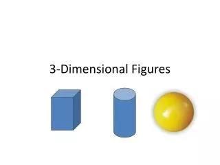
12.1 3-Dimensional Figures . Objectives. Use orthogonal drawings of 3-dimensional figures to make models Identify and use 3-dimensional figures. Orthogonal Drawings. To illustrate a 3-dimensional figure with 2-dimensional views we use a method called orthogonal drawings.

E N D
Objectives • Use orthogonal drawings of 3-dimensional figures to make models • Identify and use 3-dimensional figures
Orthogonal Drawings • To illustrate a 3-dimensional figure with 2-dimensional views we use a method called orthogonal drawings. • Orthogonal drawings are composite views of the top, left, front, and right sides of an object. Use the applets below to get a better understanding. • 3-D Object Viewer • Guess the View • Coloring 3-D Sides • Coloring 2-D Sides • Rotating Blocks
Example 1a: Draw the back view of a figure given its orthogonal drawing. If possible, use blocks to make a model. Then use your model to draw the back view. Recognize that bolder linesrepresent breaks in the surface.
Example 1a: The top view indicates 1 row of different heights and 1 column in the front right. The front view indicates that there are four standing columns. The first column to the left is 2 blocks high, the second column is 3 blocks high, the third column is 2 blocks high, and the fourth column to the far right is 1 block high. The bolder segments indicate breaks in the surface. The right view indicates that the front right column is only 1 block high. The bolder segments indicate breaks in the surface. Check the left side of your model. The back left column is 2 blocks high. The bolder segments indicate breaks in the surface.
Example 1a: Check to see that all views correspond to the model. Now that your model is accurate, turn it around to the back and draw what you see. The blocks are flush, so no heavy segments are needed. Answer:
Example 1b: Draw the corner view of the figure. Turn your model so you are looking at the corners of the blocks. The lowest columns should be in the front so the differences in height between the columns are visible. Connect the dots on isometric dot paper to represent the edges of the solid. Shade the tops of each column.
Example 1b: Answer:
Your Turn: a.Given its orthogonal drawing draw the back view of the figure. Answer:
Properties of Polyhedra • Apolyhedronis a solid bounded by polygons called faces which enclose a single region of space. • An edge of a polyhedron is a line segment formed by the intersection of two faces. • A vertex of a polyhedron is a point where three or more edges meet. • The plural of polyhedron is either polyhedraor polyhedrons.
Identifying Polyhedra • Decide whether each of the solids below is a polyhedron. If so, count the number of faces, vertices, and edges of the polyhedron.
This is a polyhedron. It has 5 faces, 6 vertices, and 9 edges. • This is not a polyhedron. Some of its faces are not polygons. • This is a polyhedron. It has 7 faces, 7 vertices, and 12 edges.
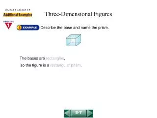
Types of Solids The prism has two parallel congruent faces called bases. The other faces are parallelograms… the pyramid has all but one of its faces (the base) intersecting at one vertex… Both solids are named by the shape of their bases followed by “prism” or “pyramid” as their surname (i.e. triangular prism and square pyramid).
Regular Prisms and Regular Polyhedra • If the bases of a prism are regular polygons, then it is called a regular prism. • If all of the faces of a polyhedron are regular congruent polygons and all of the edges are congruent then it is called a regular polyhedron.
Platonic Solids • There are five (5) regular polyhedra called Platonic Solidsnamed after the Greek mathematician and philosopher, Plato. • The five Platonic Solids are a regular tetrahedron (see above),
Platonic Solids aregular dodecahedron acube (6 faces) aregular octahedron (8 faces), and anicosahedron.
Example 2a: Identify the solid. Name the bases, faces, edges, and vertices. The bases are rectangles and the four remaining faces are parallelograms.
Answer:This solid is a rectangular prism. Bases:Faces:Edges:Vertices: A, B, C, D, E, F, G, H Example 2a:
Answer:This solid is a cylinder.Bases: Example 2b: Identify the solid. Name the bases, faces, edges, and vertices. The bases are circular and congruent.
Answer:This solid is a triangular pyramid.Base:Faces:Edges:Vertices: A, B, C, D Example 2c: Identify the solid. Name the bases, faces, edges, and vertices. The base is a triangle, and the remaining three faces meet at a point.
Answer:triangular prismBases:Faces:Edges:Vertices: A, B, C, D, E, F, G Your Turn: a.Identify the solid. Name the bases, faces, edges, and vertices.
Answer:cylinder Bases: Your Turn: b.Identify the solid. Name the bases, faces, edges, and vertices.
Your Turn: c.Identify the solid. Answer:pentagonal pyramid
Cross Sections • Imagine a plane slicing through a solid. The intersection of the plane and the solid is called a cross section. For instance, the diagram above shows that the intersection of a plane and a sphere is a circle.
Describing Cross Sections • Describe the shape formed by the intersection of the plane and the cube. This cross section is a square.
Describing Cross Sections • Describe the shape formed by the intersection of the plane and the cube. This cross section is a pentagon.
Describing Cross Sections • Describe the shape formed by the intersection of the plane and the cube. This cross section is a triangle.
Example 3: A customer orders a two-layer sheet cake. Describe the possible cross sections of the cake.
Example 3: Answer: If the cake is cut horizontally, the cross section will be a rectangle. If the cake is cut vertically, the cross section will also be a rectangle.
Example 3: A solid cone is going to be sliced so that the resulting flat portion can be dipped in paint and used to make prints of different shapes. How should the cone be sliced to make prints of a circle, triangle, and an oval? Answer: If the cone were to be cut parallel to the base, the cross-section would be a circle.
Example 3: Answer:If the cone were to be cut perpendicular to the base, the slice would be a triangle. If the cone were to be cut on an angle to the base, the slice would be an oval.
Assignment • Pg. 640 #11 - 14, 16 – 21, 25 - 30