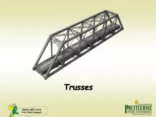
TRUSSES SAMPLE QUESTIONS
TRUSSES SAMPLE QUESTIONS. 4 m. 4 m. 4 m. E. D. 4 m. r=400 mm. H. G. C. F. 4 m. B. 16 kN. 4 m. A.

TRUSSES SAMPLE QUESTIONS
E N D
Presentation Transcript
TRUSSES SAMPLE QUESTIONS
4 m 4 m 4 m E D 4 m r=400 mm H G C F 4 m B 16 kN 4 m A 1. The crane in the figure consists of a planar truss. Determine the forces in members DE, DG and HG when the crane supports a 16 kN load, indicate whether the members work in tension (T) or compression (C).
FCJ FFJ Cut FG FBC
3. Determine the forces in members CD, CJ and DJ, state whether they work in tension (T) or compression (C).
I. Cut 3 m T FJI FDJ FCD Ax Ay
T Ax Ay II. Cut FKJ FCJ FCD
4. The truss shown consists of 45° triangles. The cross members in the two center panels that do not touch each other are slender bars which are incapable of carrying compressive loads. Identify the two tension members in these panels and determine the forces they support. Also determine the force in member MN.
I. Cut Ax II. Cut By Ay
Ux Vy Uy
III. Cut II. Cut I. Cut IV. Cut Vy=20 kN Uy=15 kN
4/47 6. Determine the forces in members DE, EI, FI and HI.
II. Cut I. Cut Gx Gy Ay
II. Cut I. Cut III. Cut
4 kN 10 kN 6 kN F E H G 2 m B C D J 2 m N K L 2 m M P A 3 m 3 m 4 m 4 m 4 m 4 m Radii of pulleys H, F and K 400 mm 20 kN 8. In the truss system shown determine the forces in members EK, LF, FK and CN, state whether they work in tension (T) or compression (C). Crossed members do not touch each other and are slender bars that can only support tensile loads.
(I) (II) (IV) 4 kN By 10 kN 10 kN 10 kN 6 kN H F E (III) G 2 m B C D 10 kN Bx J 10 kN 20 kN 2 m N K L 10 kN 2 m M P A Ax 3 m 3 m 4 m 4 m 4 m 4 m Radii of pulleys H, F and K 400 mm
2 kN 2 kN 2 kN 5 kN 3 E C G F D 4 1 kN 4 m O N H B M 4 m A I J L K 2 kN 2 kN 2 kN 3 m 3 m 3 m 3 m 9. Determine the forces in members EF, NK and LK.
3 kN 2 kN 2 kN 2 kN E C 4 kN G F D From the equilibrium of whole truss Ax, Ay and Iy are determined 1 kN 4 m I. Cut Top Part N O M H B FMN FBN FHO FMO FBA 4 m I. Cut SMH=0 FAB is determined FHI A Ax I J L K 2 kN 2 kN 2 kN Ay Iy 3 m 3 m 3 m 3 m
3 kN 2 kN 2 kN 2 kN FEF E C 4 kN G F D 1 kN FMF 4 m II. Cut Top Part II. Cut SMM=0 FEF and FMFare determined N O M H B FMN FMO FBN FBA 4 m A I J L K 2 kN 2 kN 2 kN 3 m 3 m 3 m 3 m
3 kN 2 kN 2 kN 2 kN FEF E C 4 kN G F D 1 kN FMF 4 m N FMO O M H B III. Cut SMN=0 FLK and FNKare determined 4 m FNK A I J K L FLK 2 kN 2 kN 2 kN 3 m 3 m 3 m 3 m III. Cut Left Side
kN G 1 m H F I P E kN kN 1 m N O M 1 m L J K D C 2 m kN kN B A 2 m 2 m 1 m 1 m 10. Determine the forces in members KN, FC and CB.
kN G III. Cut I. Cut 1 m H F I P E kN kN 1 m N O M 1 m J K D C L II. Cut 2 m kN kN IV. Cut B A Ax Forces in KN, FC and CB. 2 m 2 m 1 m 1 m By Ay