Download

1 / 119
1.22k likes | 1.53k Views
CSC 3910 Software Engineering. Spring 2011. Time: 1:30 to 2:20. Meeting Days: MWF. Location: Oxendine 1256. Textbook : Fundamentals of Software Engineering , Author: Carlo Ghezzi, et al , 2003, Pearson. Design and Software Architecture. Outline. What is design

E N D
CSC 3910 Software Engineering Spring 2011 Time: 1:30 to 2:20 Meeting Days: MWF Location: Oxendine 1256 Textbook: Fundamentals of Software Engineering, Author: Carlo Ghezzi, et al, 2003, Pearson Design and Software Architecture Ch. 4
Outline • What is design • How can a system be decomposed into modules • What is a module’s interface • What are the main relationships among modules • Prominent software design techniques and information hiding • The UML collection of design notations • Design of concurrent and distributed software • Design patterns • Architectural styles • Component based software engineering Ch. 4
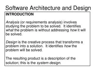
What is design? • Provides structure to any artifact • Decomposes system into parts, assigns responsibilities, ensures that parts fit together to achieve a global goal • Design refers to both an activity and the result of the activity Ch. 4
Two meanings of "design“ activity in our context • Activity that acts as a bridge between requirements and the implementation of the software • Activity that gives a structure to the artifact • e.g., a requirements specification document must be designed • must be given a structure that makes it easy to understand and evolve Ch. 4
The sw design activity • Defined as system decomposition into modules • Produces a Software Design Document • describes system decomposition into modules • Often a software architecture is produced prior to a software design Ch. 4
Software architecture • Shows gross structure and organization of the system to be defined • Its description includes description of • main components of a system • relationships among those components • rationale for decomposition into its components • constraints that must be respected by any design of the components • Guides the development of the design Ch. 4
Two important goals • Design for change (Parnas) • designers tend to concentrate on current needs • special effort needed to anticipate likely changes • Product families (Parnas) • think of the current system under design as a member of a program family Ch. 4
Sample likely changes? (1) • Algorithms • e.g., replace inefficient sorting algorithm with a more efficient one • Change of data representation • e.g., from binary tree to a threaded tree (see example) • 17% of maintenance costs attributed to data representation changes (Lientz and Swanson, 1980) Ch. 4
Example Ch. 4
Sample likely changes? (2) • Change of underlying abstract machine • new release of operating system • new optimizing compiler • new version of DBMS • … • Change of peripheral devices • Change of "social" environment • new tax regime • EURO vs national currency in EU • Change due to development process (transform prototype into product) Ch. 4
Product families • Different versions of the same system • e.g. a family of mobile phones • members of the family may differ in network standards, end-user interaction languages, … • e.g. a facility reservation system • for hotels: reserve rooms, restaurant, conference space, …, equipment (video beamers, overhead projectors, …) • for a university • many functionalities are similar, some are different (e.g., facilities may be free of charge or not) Ch. 4
Design goal for family • Design the whole family as one system, not each individual member of the family separately Ch. 4
Sequential completion: the wrong way • Design first member of product family • Modify existing software to get next member products Ch. 4
Requirements Requirements Requirements 1 1 1 2 2 2 Version 1 3 Version 1 3 4 3 4 6 4 Version 1 Version 2 5 7 Version 3 5 Version 2 Sequential completion:a graphical view intermediate design final product Ch. 4
How to do better • Anticipate definition of all family members • Identify what is common to all family members, delay decisions that differentiate among different members • We will learn how to manage change in design Ch. 4
Module • A well-defined component of a software system • A part of a system that provides a set of services to other modules • Services are computational elements that other modules may use Ch. 4
Questions • How to define the structure of a modular system? • What are the desirable properties of that structure? Ch. 4
Modules and relations • Let S be a set of modules S = {M1, M2, . . ., Mn} • A binary relation r on S is a subset of S x S • If Mi and Mj are in S, <Mi, Mj> r can be written as Mi r Mj Ch. 4
Relations • Transitive closure r+ of r Mi r+ Mj iff Mi r Mj or Mk in S such that Mi r Mk and Mk r+ Mj (We assume our relations to be irreflexive, i.e., Mi r Mi cannot hold) • r is a hierarchy iff there are no two elements Mi, Mj s.t. Mi r+ Mj Mj r+ Mi • For two modules A and B, A CALLS+ B implies that either A CALLS B directly or A CALLS B indirectly Ch. 4
USES • Mi uses Mj if Mj requires the presence of Mj, because Mj provides a resource Mi needs to accomplish its task. • If Mi USES Mj then Mi is a client of Mj and Mj is called a server. • A USES relationship is established if module Mi accesses a resouce provided by module Mj • Mi USES Mj if Mi contains a call to a procedure contained in Mj Ch. 4
Relations • USES is should be a hierarchy • Relations can be represented as graphs • A hierarchy is a DAG (directed acyclic graph) a graph a DAG Ch. 4
The USES relation • A uses B • A requires the correct operation of B • A can access the services exported by B through its interface • it is “statically” defined • A depends on B to provide its services • example: A calls a routine exported by B • A is a client of B; B is a server Ch. 4
Desirable property • USES should be a hierarchy • Hierarchy makes software easier to understand • we can proceed from leaf nodes (who do not use others) upwards • They make software easier to build • They make software easier to test Ch. 4
Hierarchy • Organizes the modular structure through levels of abstraction • Each level defines an abstract (virtual) machine for the next level • level can be defined precisely • Mi has level 0 if no Mj exists s.t. Mi r Mj • let k be the maximum level of all nodes Mj s.t. Mi r Mj. Then Mi has level k+1 Ch. 4
IS_COMPONENT_OF • Used to describe a higher level module as constituted by a number of lower level modules • A IS_COMPONENT_OF B • B consists of several modules, of which one is A • B COMPRISES A • MS,i={Mk|MkSMk IS_COMPONENT_OF Mi} we say that MS,i IMPLEMENTS Mi Ch. 4
M M M M M M 6 8 9 5 1 7 M M M 3 4 2 M M M 4 2 3 M M M M M M 1 6 8 9 5 7 (IS_COMPONENT_OF) (COMPRISES) A graphical view They are a hierarchy Ch. 4
Product families • Careful recording of (hierarchical) USES relation and IS_COMPONENT_OF supports design of program families Ch. 4
Interface vs. implementation (1) • To understand the nature of USES, we need to know what a used module exports through its interface • The client imports the resources that are exported by its servers • Modules implement the exported resources • Implementation is hidden to clients Ch. 4
Interface vs. implementation (2) • Clear distinction between interface and implementation is a key design principle • Supports separation of concerns • clients care about resources exported from servers • servers care about implementation • Interface acts as a contract between a module and its clients Ch. 4
Interface vs. implementation (3) interface is like the tip of the iceberg Ch. 4
Information hiding • Basis for design (i.e. module decomposition) • Implementation secrets are hidden to clients • They can be changed freely if the change does not affect the interface • Golden design principle • INFORMATION HIDING • Try to encapsulate changeable design decisions as implementation secrets within module implementations Ch. 4
How to design module interfaces? • Example: design of an interpreter for language MINI • We introduce a SYMBOL_TABLEmodule • provides operations to • CREATE an entry for a new variable • GET the value associated with a variable • PUT a new value for a given variable • the module hides the internal data structure of the symbol table • the data structure may freely change without affecting clients Ch. 4
Interface design • Interface should not reveal what we expect may change later • It should not reveal unnecessary details • Interface acts as a firewall preventing access to hidden parts Ch. 4
Prototyping • Once an interface is defined, implementation can be done • first quickly but inefficiently • then progressively turned into the final version • Initial version acts as a prototype that evolves into the final product Ch. 4
More on likely changesan example • Policies may be separated from mechanisms • mechanism • ability to suspend and resume tasks in a concurrent system • policy • how do we select the next task to resume? • different scheduling policies are available • they may be hidden to clients • they can be encapsulated as module secrets Ch. 4
Design notations • Notations allow designs to be described precisely • They can be textual or graphic • We illustrate two sample notations • TDN (Textual Design Notation) • GDN (Graphical Design Notation) • We discuss the notations provided by UML Ch. 4
TDN & GDN • Illustrate how a notation may help in documenting design • Illustrate what a generic notation may look like • Are representative of many proposed notations • TDN inherits from modern languages, like Java, Ada, … Ch. 4
An example Ch. 4
Comments in TDN • May be used to specify the protocol to be followed by the clients so that exported services are correctly provided • e.g., a certain operation which does the initialization of the module should be called before any other operation • e.g., an insert operation cannot be called if the table is full Ch. 4
Example (cont.) Ch. 4
Benefits • Notation helps describe a design precisely • Design can be assessed for consistency • having defined module X, modules R and T must be defined eventually • if not incompleteness • R, T replace X • either one or both must use Y, Z Ch. 4
Example: a compiler moduleCOMPILER exports procedure MINI (PROG: in file of char; CODE: out file of char); MINI is called to compile the program stored in PROG and produce the object code in file CODEimplementation A conventional compiler implementation. ANALYZER performs both lexical and syntactic analysis and produces an abstract tree, as well as entries in the symbol table; CODE_GENERATOR generates code starting from the abstract tree and information stored in the symbol table. MAIN acts as a job coordinator.is composed of ANALYZER, SYMBOL_TABLE,ABSTRACT_TREE_HANDLER, CODE_GENERATOR, MAIN end COMPILER Ch. 4
Other modules module MAINuses ANALYZER, CODE_GENERATORexports procedure MINI (PROG: in file of char; CODE: out file of char); … end MAIN module ANALYZERuses SYMBOL_TABLE, ABSTRACT_TREE_HANDLERexports procedure ANALYZE (SOURCE: in file of char); SOURCE is analyzed; an abstract tree is produced by using the services provided by the tree handler, and recognized entities, with their attributes, are stored in the symbol table. ... end ANALYZER Ch. 4
Other modules module CODE_GENERATOR uses SYMBOL_TABLE, ABSTRACT_TREE_HANDLER exports procedure CODE (OBJECT: out file of char); The abstract tree is traversed by using the operations exported by the ABSTRACT_TREE_HANDLER and accessing the information stored in the symbol table in order to generate code in the output file. … end CODE_GENERATOR Ch. 4
X's decomposition Ch. 4
Categories of modules • Functional modules • traditional form of modularization • provide a procedural abstraction • encapsulate an algorithm • e.g. sorting module, fast Fourier transform module, … Ch. 4
Categories of modules (cont.) • Libraries • a group of related procedural abstractions • e.g., mathematical libraries • implemented by routines of programming languages • Common pools of data • data shared by different modules • e.g., configuration constants • the COMMON FORTRAN construct Ch. 4
Categories of modules (cont.) • Abstract objects • Objects manipulated via interface functions • Data structure hidden to clients • Abstract data types • Many instances of abstract objects may be generated Ch. 4
Abstract objects: an example • A calculator of expressions expressed in Polish postfix form a*(b+c) abc+* • a module implements a stack where the values of operands are shifted until an operator is encountered in the expression (assume only binary operators) Ch. 4