Master PIC18 Interrupt Programming Guide
Learn about interrupts, timers, external hardware, serial communication, and interrupt priorities in PIC18. Dive into ISRs, IVTs, enabling/disabling interrupts, and assembly language programming. Understand the differences between interrupts and polling methods.

Master PIC18 Interrupt Programming Guide
E N D
Presentation Transcript
PIC18 Interrupt Programming “Explain the interrupts, timer interrupts, external hardware interrupts, serial communication interrupts and the interrupts priority”
Objectives • Contra and compare interrupts versus pooling • Explain the purpose of the ISR • List all the major interrupts of the PIC18 • Explain the purpose of the IVT • Enable and disable PIC18 interrupts • Program the PIC18 interrupt using assembly language
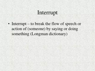
Interrupt • Whenever any device needs the microcontroller’s service the device notifies it by sending an interrupt signal. Upon receiving an interrupt signal, the microcontroller stops whatever it is doing and serve the device. The program associated with the interrupt is called ISR (interrupt service routine) or interrupt handler. • Each device can get the attention of the microcontroller based on the priority assign to it. • Can ignore a device request for service
Polling • The microcontroller continuously monitors the status of a given device; when the status condition met, it performs the service. After that, it moves on to monitor the next device until each one is service. • Cannot assign priority because it checks all devices in a round-robin fashion. • Cannot ignore a devices for service
Interrupt Service Routine (ISR) Interrupt Vector Table for the PIC18 Fixed Location in Memory
Step in Executing an Interrupt • It finishes the instruction it is executing and saves the address of the next instruction (program counter) on the stack • It jumps to a fixed location in memory (interrupt vector table (IVT)). The IVT directs the microcontroller to the address of the ISR • The microcontroller gets the address of the ISR from the IVT and jumps to it. It start to execute the interrupt service subroutine until it reaches the last instruction of the subroutine - RETFIE (Return from Interrupt Exit) • Upon executing the RETFIE instruction, the microcontroller returns to the place where it was interrupted
Sources of Interrupt • Each Timers • 3 interrupts for external hardware. Pin RB0 (INT0), RB1 (INT1) and RB2 (INT2) • 2 interrupts for serial communication (Receive and Transmit) • The PORTB-Change interrupt (RB4-RB7) • The ADC • The CCP
Enable and Disable an Interrupt BSF INTCON,GIE BCF INTCON,GIE
Timer Interrupts Timer Interrupt Flag Bits and Associated Registers INTCON Register with Timer0 Interrupt Enable and Interrupt Flag
Program 11-1 (pg 430) ORG 0000H GOTO MAIN ORG 0008H BTFSS INTCON,TMR0IF RETFIE GOTO T0_ISR ORG 00100H MAIN BCF TRISB,5 CLRF TRISD SETF TRISC MOVLW 0x08 MOVWF T0CON MOVLW 0xFF MOVWF TMR0H MOVLW 0xF2 MOVWF TMR0L BCF INTCON,TMR0IF BSF T0CON,TMR0ON BSF INTCON,TMR0IE BSF INTCON,GIE OVER MOVFF PORTC,PORTD BRA OVER T0_ISR ORG 200H MOVLW 0xFF MOVWF TMR0H MOVLW 0xF2 MOVWF TMR0L BTG PORTB,5 BCF INTCON,TMR0IF RETFIE END Timer0 Interrupt
External Hardware Interrupts Hardware Interrupt Flag Bits and Associated Registers Positive-edge-triggered interrupt PIC18 External Hardware Interrupt Pins
Program 11-4 (pg 440) ORG 0000H GOTO MAIN ORG 0008H BTFSS INTCON,INT0IF RETFIE GOTO T0_ISR ORG 00100H MAIN BCF TRISB,7 BSF TRISB, INT0 CLRF TRISD SETF TRISC BSF INTCON,INT0IE BSF INTCON,GIE OVER MOVFF PORTC,PORTD BRA OVER T0_ISR ORG 200H BTG PORTB,7 BCF INTCON,INT0IF RETFIE END BCF INTCON2,INTEDG1 Hardware Interrupt Negative-edge-trigerred
Serial Communication Interrupts Serial Port Interrupt Flag Bits and Associated Registers PIE1 Register Bits Holding TXIE and RCIE
Program 11-6 (pg 446) ORG 0000H GOTO MAIN ORG 0008H BTFSC PIR1,TXIF BRA TX_ISR RETFIE ORG 00100H MAIN SETF TRISD MOVLW 0x20 MOVWF TXSTA MOVLW D'15' MOVWF SPBRG BCF TRISC, TX BSF RCSTA, SPEN BSF PIE1,TXIE BSF INTCON,PEIE BSF INTCON,GIE OVER BRA OVER END Serial Port Interrupt ORG 0040H TX_ISR MOVWFF PORTD,TXREG RETFIE Enable peripheral Interrupt
PORTB-Change Interrupt INTCON Register * Use in Keypad Interfacing * Status: H-L or L-H
Differences Between External Hardware and PORTB-Change Interrupt
Interrupt Priority (Cont’d) Upon Power-on Reset
Please see Program 11-10 (pg 459) and Program 11-11 (pg 460)
End Of Chapter “Never interrupt your enemy when he/she is making a mistake“