Download
1 / 55
550 likes | 650 Views
Explore key concepts of routing protocols, limitations of technologies on routing, dynamic VPN solutions like DMVPN, and configuration of RIPng for IPv6 support. Differentiate between IGP and EGP routing protocols, understand route summarization, convergence, and scalability in enterprise network infrastructure.

E N D
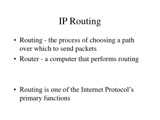
Implementing CiscoIP Routing (ROUTE)Foundation Learning GuideCCNP ROUTE 300-101 Basic Network and Routing Concepts Chapter 1
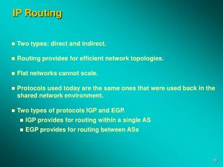
Basic Network and Routing Concepts • An overview of routing protocols that focuses on characteristics that describe their differences. • Describe how limitations of different underlying technologies affect routing protocols. • Closer look at how Layer 2 and Layer 3 VPNs affect routing protocols. • Dynamic Multipoint Virtual Private Network (DMVPN) is introduced as a scalable VPN solution • Configuration of a simple routing protocol RIPng, which supports Internet Protocol version 6 (IPv6).
Differentiating Routing Protocols Upon completing this section, you will be able to: • Identify general enterprise network infrastructure • Describe the role of dynamic routing protocols within the enterprise network infrastructure • Identify the major areas of differences among routing protocols • Describe the differences between IGP and EGP routing protocols • Describe the different types of routing protocols • Identify the importance of convergence • Describe route summarization • Describe what influences routing protocol scalability
Enterprise Network Infrastructure • Network infrastructure of enterprises today can be complicated at first glance. • A large number of interconnected devices and differences between physical and logical topologies are just two reasons for this complexity. • Devices can be mapped into different areas according to the functionality that they provide in the network infrastructure
Figure 1-1Enterprise Network Infrastructure Enterprise Campusprovides access to the network communications services and resources to end users and devices. Single geographic location, designed using a hierarchical model: Access, Distribution and Core layers Enterprise edge provides remote sites with access to the same network services as users at the main site, aggregates private WAN links, VPN connections & Internet connectivity
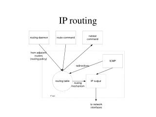
Figure 1-2Role of Dynamic Routing Protocols The basic objective of routing protocols is to exchangenetwork reachability information between routers and dynamically adapt to network changes.
Figure 1-3IGP versus EGP Interior Gateway Protocols (IGP): used within the organization, and they exchange the routes within an AS Exterior Gateway Protocols (EGP): exchanging routes between different autonomous systems. Border Gateway Protocol (BGP)
Routing protocols can be divided into the following groups: • Distance vector protocols Determines the: • Direction (vector, Next hop or Exit interface) • Distance (such as link cost or number of hops) to any link in the network. • Distance vector protocols use routers as signposts along the path to the final destination. Uses Bellman-Ford algorithm • Link-state protocols: The link-state approach uses the Shortest Path First (SPF) algorithm to create an abstract of the exact topology of the entire network or at least within its area. A link-state routing protocol is like having a complete map of the network topology.
Convergencedescribes the process of when routers notice change in the network, exchange the information about the change, and perform necessary calculations to reevaluate the best routes. Convergence time affected by: Routing protocol timers Route summarization A converged network describes the state of the network in which allrouters have the same view on the network topology. Convergence time describes how fast network devices can reach the state of convergence after a topology change.
Route summarization enables you to reduce routing overhead and improve stability and scalabilityof routing by reducing the amount of routing information that is maintained and exchanged between routers. • The purpose of route summarization is to squeeze several subnets into one aggregate entry that describes all of them. As shown in Figure 1-5 , route summarization reduces the size of routing tables • Different routing protocols support different route summarization options. • IP addresses must be hierarchically assigned in contiguous blocks across the network.
Route Protocol Scalability • As a network grows and becomes larger, the risk of routing protocol instability or long convergence times becomes greater. • Scalabilitydescribes the ability of a routing protocol to support further network growth. • Scalability factors include: • Number of routes • Number of adjacent neighbors • Number of routers in the network • Network design • Frequency of changes • Available resources (CPU and memory) • OSPFsupports the use of hierarchical areas that divide one large network into several subdomains. • EIGRP supports the configuration of stub routers to optimize information exchange process and improve scalability.
Understanding Network Technologies • You can establish routing protocols over a variety of different network technologies. • It is important to consider the limitations of a specific solution and how it affects routing protocol deployments and operation. • Upon completing this section, you will be able to: • Differentiate traffic types • Differentiate IPv6 address types • Describe ICMPv6 neighbor discovery • Differentiate network types • Describe the impact of NBMA (Non-broadcast Multiaccess) on routing protocols • Describe how the Internet breaks enterprise routing
Traffic types: • Unicast: Unicast addresses are used in a one-to-one context. Unicast traffic is exchanged only between one sender and one receiver. • Multicast: Multicast addresses identify a group of interfaces across different devices. Traffic that is sent to multiple destinations at the same time. • IPv4 multicast addresses is 224.0.0.0–239.255.255.255. • IPv6 reserved multicast addresses have the prefix FF00::/8. • Anycast: IPv6 anycast address is assigned to an interface on more than one node. Packet is routed to the nearest interface that has this address. • A common use case for anycast is the Internet DNS server. • Broadcast: IPv4 broadcast addresses are used when sending traffic to all devices in the subnet. IPv6 does not use a broadcast address • Local broadcast address 255.255.255.255. • Directed broadcast address N.N.N.255
Traffic Types • Early routing protocols used only broadcasts to exchange routing information. • All modern IGPs use multicast addresses to perform neighbor discovery, exchange routing information, and send updates.
IPv6 Address Types There are several different basic types of IPv6 addresses. It is important that you are familiar with them, since some of them are also used by routing protocols. RFC 3587 specifies 2000::/3 to be global unicast address space that the IANA may allocate to the Regional Internet Registries (RIRs).
IPv6 Global Unicast Address • The following displays how IPv6 global unicast addresses are allocated by the IANA. • Only a small portion (12.5%) of the IPv6 address space is being allocated to the Registries in the range of 2001::/16.
IPv6 Global Unicast Address • The global unicast address typically consists of: • A 48-bit global routing prefix • A 16-bit subnet ID • A 64-bit interface ID (typically in EUI-64 bit format discussed later). Subnet ID Global Routing Prefix Interface ID /23 /32 /48 /64 Registry ISP Prefix Site Prefix Subnet Prefix
Network Types Not all Layer 2 network topologies support all traffic types. Because unsupported traffic types influence the operation of routing protocols, it is important to be aware of the limitations of specific network topologies. Point-to-point network: A network that connects a single pair of routers. A serial link is an example of a point-to-point connection. Broadcast network: A network that can connect many routers along with the capability to address a single message to all of the attached routers. Ethernet is an example of a broadcast network. Non-broadcast Multiaccess (NBMA) network: A network that can support many routers but does not have broadcast capability. (ex: Frame Relay) The sender needs to create an individual copy of the same packet for each recipient if it wishes to inform all connected neighbors.
Frame Relay NBMA OperationFrame Relay Star Topologies Star Topology (Hub and Spoke) The simplest WAN topology is a star. In this topology, SPAN Engineering Company has a central site in Chicago that acts as a hub and hosts the primary services.
Frame Relay OperationFrame Relay Mesh Topologies Using Frame Relay Mesh, a network designer can build multiple connections simply by configuring additional VCs on each existing physical link. This software upgrade grows the star topology to a full mesh topology without the expense of additional hardware or dedicated lines.
NBMA Networks If you use a single Frame Relay, multipoint interface to interconnect multiple sites, reachability issues may be a problem because of the NBMA nature of Frame Relay. The Frame Relay NBMA topology can cause the following issues: Split horizon: For distance vector routing protocols, the split-horizon rule reduces routing loops. As illustrated in Figure 1-9, itprevents a routing update that is received on an interface from being forwarded out of the same interface. The hub router receives the update on its physical interface but cannot forward it through the same interface to other spoke routers. Split horizon is not a problem if there is a single PVC on a physical interface because this type of connection would be point-to-point.
Neighbor discovery: OSPF over NBMA networks works in a nonbroadcast network mode by default, and neighbors are not automatically discovered. You can statically configure neighbors, but an additional configuration is required to manually configure the hub as a Designated Router (DR). OSPF treats an NBMA network like Ethernet by default, and on Ethernet, a DR is needed to exchange routing information between all routers on a segment. Therefore, only the hub router can act as a DR because it is the only router that has PVCs with all other routers.
Broadcast replication: For multipoint connections over a single interface that terminates at multiple PVCs, the router must replicate broadcast packets, such as routing update broadcasts, on each PVC to the remote routers. These replicated broadcast packets consume bandwidth and cause significant latency variations in user traffic.
Subinterfaces: • Subinterfacesovercome some limitations of NBMA networks. • You can choose between two different types of subinterfaces: • Point-to-point subinterfaces: Each subinterface, which provides connectivity between two routers, uses its own subnet for addressing. Connectivity looks just like several physical point-to-point links, no issues with neighbor discovery and the split-horizon rule. • Point-to-multipoint subinterfaces: One subnet is shared between all virtual circuits. Because private address space is normally used for addressing, saving address space is not a significant benefit. Point-to-point subinterfaces are the preferred and recommended choice.
Routing Over the Internet • Principles of Static Routing • A static route can be used in the following circumstances: • When it is undesirable to have dynamic routing updates forwarded across slow bandwidth links, such as a dialup link. • When the administrator needs total control over the routes used by the router. • When a backup to a dynamically recognized route is necessary. • When it is necessary to reach a network accessible by only one path (a stub network). • When a router connects to its ISP and needs to have only a default route pointing toward the ISP router, rather than learning many routes from the ISP. • When a router is underpowered and does not have the CPU or memory resources necessary to handle a dynamic routing protocol. Figure 1-11Configuring Static Routing
Configuring a Static Default Route • In some circumstances, a router does not need to recognize the details of remote networks. • The router is configured to send all traffic in a particular direction; this is known as a default route. • To create a static default route, use the normal ip route command, but with the destination network and its subnet mask both set to 0.0.0.0. • In Figure 1-12 , to reach the 172.16.1.0/24 network, Router B still needs a static route pointing out its S0/0/0 interface. • Entering the show ip route command on Router A in Figure 1-12 returns the information shown in Example 1-1 .
Basic PPP Overview • Point-to-Point Protocol (PPP) has several advantages over its predecessor High-Level Data Link Control (HDLC). The following example enables PPP encapsulation on interface serial 0/0/0: R1# configure terminal R1(config)# interface serial 0/0/0 R1(config-if)# encapsulation ppp • PPP Authentication Overview • RFC 1334 defines two protocols for authentication, PAP and CHAP. • PAP is a very basic two-way process, there is no encryption. The username and password are sent in plaintext. • CHAP authentication sends a challenge to the remote device. • The remote device must encrypt the challenge valuewith a shared secret and return the encrypted value and its name to the local router in a response message. • LCP (Link Control Protocol) establishes the link & chooses the authentication protocol.
PPPoE • PPP can be used on all serial links including those links created with older dialup analog and ISDN modems. • In addition, ISPs often use PPP as the data-link protocol over broadband connections like DSL. • With PPP enabled, ISPs can use PPP to assign each customer one public IPv4 address. • During the CHAP to authenticate customers ,ISPs can check accounting records. • Ethernet links do not natively support PPP. • A solution to this problem was created: PPP over Ethernet (PPPoE). • PPPoE allows the sending of PPP frames encapsulated inside Ethernet frames. • The modem converts the Ethernet frames to PPP frames by stripping the Ethernet headers. • The modem then transmits the PPP frames on the ISP’s DSL network. • ISP could continue to use the same authentication model as with analog and ISDN. • To create a PPP tunnel, the configuration uses a dialer interface. • The PPP configuration is placed on the dialer interface, not on the physical interface. • The PPP CHAP configuration usually defines one-way authentication. • The physical Ethernet interface then enabled with the command pppoe enable • The maximum transmission unit (MTU) should be reduced to 1492, versus the • default of 1500, to accommodate the PPPoE headers.
Frame Relay is a switched WAN technology where virtual circuits (VCs) are created by a service provider (SP) through the network. • VCs provide a bidirectional communication path from one device to another. • VCs are identified by DLCIs • DLCI values typically are assigned by the Frame Relay service provider • Frame Relay allows multiple logical VCs to be multiplexed over a single physical interface. • Frame Relay is statistically multiplexed, meaning that it transmits only one frame at a time, but that many logical connections can co-exist on a single physical line.
Using Frame Relay Mesh, a network designer can build multiple connections simply by configuring additional VCs on each existing link This software upgrade grows the star topology to a full mesh topology without the expense of additional hardware or dedicated lines. Star Topology (Hub and Spoke) The simplest WAN topology is a star. In this topology, SPAN Engineering Company has a central site in Chicago that acts as a hub and hosts the primary services.
Split horizon is disabled by default on Frame Relay physical interfaces. • Therefore, routes from Router R2 can be sent to Router R3, and vice versa. • Note that Inverse ARP does not provide dynamic mapping for the communication between Routers R2 and R3 because they are not connected with a PVC. • You must configure this mapping manually. 192.168.1.101 255.255.255.0 192.168.1.102 102 broadcast Figure 1-16EIGRP on a Physical Frame Relay Interface
MPLS • MPLS (Multiprotocol Label Switching) is a transport mechanism that is developed to carry data over the packet-switched network. • Designed to offer a great level of flexibility to operate seamlessly with any Layer 3 or Layer 2 technology. • VPN service enables service providers and large enterprises to build flexible, scalable, and secure VPNs. • MPLS is a switching mechanism. • A 32 bit header (label) is inserted by the provider (PE) router. • Packets are switched through the MPLS network. • The label is removed by the PE at the other end of the MPLS network. • To the customer, it looks like a Layer 2 or Layer 3 connection.
Two types of MPLS VPNs have been developed: 1. The Layer 2 MPLS VPN backbone solution is providing the Layer 2 service across the backbone, R1 and R2 are connected together directly using the same IP subnet. If you deploy a routing protocol over the Layer 2 MPLS VPN, neighbor adjacency is established between your R1 and R2 routers. The figure presents the connectivity through the backbone. 2. The Layer 3 MPLS VPN backbone solution is providing the Layer 3 service across the backbone, R1 and R2 are connected to ISP edge routers. A separate IP subnet is used on each side. If you deploy a routing protocol over this VPN, service providers need to participate in it. Neighbor adjacency is established between your R1 and the closest PE router and between your R2 and it’s closest PE router. Figure 1-17 Layer 3 MPLS VPN Solutions
A GRE tunnel (Generic Routing Encapsulation) a point-to-point tunnel developed by Cisco that allows a wide variety of passenger protocols to be transported over the IP network. • It comprises three main components: • A passenger protocol or encapsulated protocol, such as IPv4 or IPv6 that is being encapsulated. • A carrier protocol, GRE in this example, that is defined by Cisco as a multiprotocol carrier protocol and described in RFC 2784. • A transport protocol, such as IP, that carries the encapsulated protocol. • GRE has the following characteristics: • GRE uses a protocol-type field in the GRE header to support the encapsulation of any OSI Layer 3 protocol (IPv4, IPv6, IPX, AppleTalk). • GRE itself is stateless. It does not include any flow-control mechanisms, by default. • GRE does not include any strong security mechanisms to protect its payload. • The GRE header, along with the tunneling IP header, creates at least 24 bytes of additional overhead for tunneled packets.
With a generic hub-and-spoke topology, you can typically implement static tunnels (typically GRE with IPsec) between central hub and remote spokes, as shown in Figure Dynamic Multipoint Virtual Private Network: • The main characteristics of the mGRE configuration are as follows: • Only one tunnel interface needs to be configured on a router to support multiple remote GRE peers. In a hub-and-spoke network, a single mGRE tunnel interface on the hub accommodates many spoke GRE peers. • In order to learn about the IP addresses of other peer, devices using mGRErequire NHRP to build dynamic GRE tunnels. Peers can also use dynamically assigned addresses that will then be used by NHRP when registering with the hub. (NHRP - Next Hop Resolution Protocol) • mGRE interfaces also support unicast, multicast, and broadcast traffic.
Multipoint GRE • An important characteristic of the DMVPN solution is scalability, which is enabled by • deploying Multipoint GRE (mGRE). mGRE technology enables a single GRE interface • to support multiple GRE tunnels and simplifies the complexity of the configuration. • Figure 1-20 shows two options for implementing mGRE functionality: • The left diagram shows the hubthat is optimized with an mGRE interface. In this setup, only a single interface is required on the hub. However, you must deploy NHRP for the hub to learn spoke addresses and correctly provision the spoke-to-hub GRE tunnels. • In the right diagram, all devices in a hub-and-spoke network use the mGRE interface. Using NHRP, these devices can establish a partial mesh or full mesh of GRE tunnels. By only configuring a single mGRE interface on each device, the configuration is greatly simplified and manageability improved.
Client-Server Protocol • NHRP is a client-server protocol, the hub acts as the server, and the spokes are clients. • NHRP is used by routers to determine the IP address of the next hop in IP tunneling networks. • NHRP creates a mapping for a tunnel IP address to the physical interface IP address for each spoke at the hub.
Secure VPN Authentication • Ensures that a message: • Comes from an authentic source and • Goes to an authentic destination Data confidentiality • Protecting data from eavesdroppers (encryption) • Aims at protecting the message contents from being intercepted by unauthenticated or unauthorized sources. Data integrity • Across the Internet, there is always the possibility that the data has been modified. Antireplay protection: • Antireplay protection verifies that each packet is unique and not duplicated. • VPN with IPsec supports • IP unicast only • IPsec with GRE supports • IP multicast • dynamic IGP routing protocols • non-IP protocols • IPsec has two encryption modes: • Tunnel mode • Transport mode
IPsec is best thought of as a set of features that protects IP data as it travels from one location to another. • IPsec can protect only the IP layer and up (transport layer and userdata). • IPsec cannot extend its services to the data link layer. • If protection of the data link layer is needed, then some form of link encryption is needed. • Encryption, Authentication and data integrity are NOT a requirement of IPsec, they’re optional (although heavily implemented) feature of IPsec.
IPsec • Security is also an important part of the DMVPN solution. • Security services are enabled by the use of the IPsec framework. • IPsec is a framework of open standards that define how to provide secure communications. • It relies on existing algorithms to implement the: • Encryption • Authentication • key exchange. • IPsec provides four important security services: • Confidentiality (encryption): The sender can encrypt the packets before transmitting them across a network. • Data integrity: The receiver can verify that the data was transmitted through the path without being changed or altered in any way. • Authentication: Authentication ensures that the connection is made with the desired communication partner. • Antireplay protection: Verifies that each packet is unique and not duplicated. • IPsec packets are protected by comparing the sequence number of the received packets with a sliding window on the destination host.
Routing and TCP/IP Operations • Routing protocols are part of the TCP/IP protocol suite, specifically at Layer 3. • Network communications requires a wide range of protocols responsible for a wide variety of tasks to ensure communications between devices. • MSS (Maximum Segment Size) , Fragmentation, and PMTUD (Path MTU Discovery) • Most transmission links enforce a small maximum packet length, 1500 Bytes, called the maximum transmission unit(MTU). • When a router receives an IPv4 packet larger than the MTU of the outgoing interface, it must fragment the packet unless the DF (Don’t Fragment) bit is set in the IPv4 header. • Fragmentation causes several issues including the following: • CPU and memory overhead in fragmentation of the packet • CPU and memory overhead in destination devices during reassembly of packets • Retransmission of the entire packet when one fragment is dropped • Firewalls that do Layer 4 through Layer 7 filteringmay have trouble processing IPv4 fragments correctly • To avoid fragmentation of an IPv4 packet • TCP MSS Sets the MTU of the outgoing interface minus 40 bytes. • The 40 bytes take into account the 20-byte IPv4 header and 20-byte TCP header. • Example: a TCP MSS of 1460, which is 1500 bytes for the Ethernet MTU, minus 20 • bytes for the IPv4 header, and minus 20 bytes for the TCP header. MSS Maximum Size Segment
Path MTU Discovery (PMTUD) was developed for the purpose of determining the lowest MTU along a path from the packet’s source to destination. PMTUD is only supported by TCP. • PMTUD is performed by a host using the full MSS on the outgoing interface: • When the TCP packets that exceeds the MTU cannot be fragmented; DF (Don’t Fragment) bit is set. • The router along the path will drop the packet and send an ICMP “Destination Unreachable” message back to the originator of the packet. • The ICMP Destination Unreachable message contains the code indicating “fragmentation needed and DF set” and the packet was dropped. • The source receives the ICMP message, reduces the size of the MSS to be within the MTU, and retransmits the message. • *The PMTUD operations for IPv6 are similar to that of PMTUD for IPv4 TCP Starvation TCP incorporates mechanisms for reliability, flow control, and congestion avoidance. • TCP tries to do its part by backing off on bandwidth, called slow start . UDP is faster and simpler data transmissions protocol, does not include these features. • UDP without any flow control mechanisms continues, potentially using up the available bandwidth given up by TCP. This is known as TCP starvation/UDP dominance .
ICMP Redirect ICMP Redirect messages are used by routers to notify the sender of a packet that there is a better route available for a particular destination. • R1 and R2, are connected to the same Ethernet segment as host PCA. • The IPv4 default gateway of PCA is the IPv4 address of router R1. • PCA sends a packet for PCX to its default gateway R1. Figure 1-23ICMP Redirect • R1 examines its routing table and determines the next hop as router R2, on the same Ethernet segment as PCA. • R1 forwards the packet out the same interface used to receive the packet from PCA. • R1 also sends an ICMP Redirect message informing PCA of a better route to PCX by way of R2. • The ICMPv6 Redirect message functions the same way as the Redirect message for ICMPv4, with one additional feature. PCA can now send IPv6 packets directly to PCB even though it is on a different IPv6 network.
Implementing RIPng • RIP is an IGP that is used in smaller networks. • A distance vector routing protocol that uses hop count (15 Max) as a routing metric. • There are three versions of RIP: RIPv1 & RIPv2 (IPv4) ,and RIPng (IPv6). • Upon completing this section, you will be able to: • Describe general RIP characteristics • Describe how to configure and verify basic RIPng • Describe how to configure RIPng to share default routes • Analyze the RIPng database • As a routing loop-prevention technique, RIP implements: • Split horizon, prevents routing information from being sent out the same interface from which it was received. • Split horizon with poison reverse is a similar technique but sends the update with a metric of 16, which is considered unreachable by RIP. • RIP is also capable of load balancing traffic over equal-cost paths. The default is four equal-cost paths.
RIP will choose the direct path—the one over the 100-Mbps link—because the destination is only 2 hops away. The hop count over the three 1-Gbps links is 4. • In this case, RIP will choose the worse path. • A more advanced protocol, such as OSPF or EIGRP, would not choose the path over the weak, 100-Mbps link. Traffic would be forwarded over the 1-Gbps links.
By default, RIPv2 automatically summarizes networks at major network boundaries, summarizing routes to the classful network address. • To modify the default RIPv2 behavior of automatic summarization, use the no auto-summary router configuration mode command: • Router(config-router)# no auto-summary • The ip summary-address ripip-address network-mask interface command is used to • summarize an address or subnet under a specific interface. AKA manual summarization • Router(config-if)# ip summary-address rip 102.0.0 255.255.0.0
There are two major differences between RIPv2 and RIPng: • RIPv2 advertises routes for IPv4 and uses IPv4 for transport, while RIPng advertises routes for IPv6 and uses IPv6 for transport. • The configuration of RIPng is quite different when compared to RIPv2 configuration
Configuring RIPng • We will begin by configuring basic RIPng on R2 using the topology in Figure 1-26 . • RIPng is already preconfigured on R1. • On R1, there is a static default route that is already configured, which routes all the unknown traffic toward the Internet. Basic RIPng Configuration Next, IPv6 routing is enabled using the ipv6 unicast-routing command. While IPv4 routing is enabled by default on Cisco routers, IPv6 routing is not.