Download
1 / 5
50 likes | 127 Views
Stave studies Parametric Cad Model. December 2 nd 2013 Christophe Bault. Stave studies – Parametric Cad Model. Why do we need parametric Cad models?

E N D
Stave studiesParametric Cad Model December 2nd2013 Christophe Bault
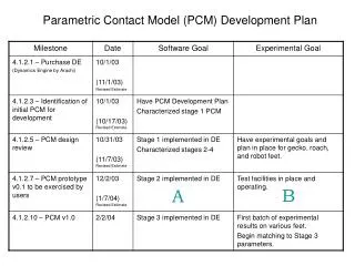
Stave studies – Parametric Cad Model • Why do we need parametric Cad models? • To define best stave in term of weight and stiffness by Ansys simulation. Parametric Cad model should allow fast iteration by changing some parameters. • Once best parameterswillbedefined, weshouldorder prototypes made by Composite Design • 2 scenarios are studied: • Sandwich stave • Composed of: • Layer 1: carbonfiber, weavedfollowingskeletonabove • Layer 2: foam • Layer 3: same as layer 1 • Staveiscured, and afterpolymerization, foamiscut in carbon fibre openings. • Filament stave • A bundle of carbonfiberiswrappedaround a mandrel. • Mandrelshouldberemovedafterstavepolymerization, to keeponly filament stave. • Compared to picture, weshouldadd 1 helicoidal filament, set by half a pitch, • few tours of filament ateachextremity, • longitudinal profile (1 flat on top+ 1 flat on bottom, or U shape)
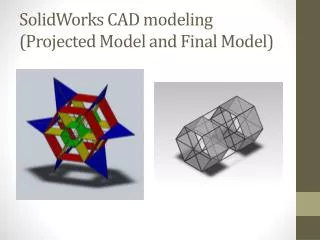
Stave studies – Parametric Cad Model • Sandwich stave • Cad model isdone: • Composed of 2d models (meansnodes are flat) • each model isrepresented by a surface modelized as neutral fibre. • Needconfirmation by FX or Fernando that 2d model canbeused on Ansys • Parameters: Wecan change length, width, angle and number of • diagonal fibres, position of stave centre (on a node or between 2 nodes), • foamthickness. • On Catia, change of parametersshouldautomaticallymodifycad model. • Unfortunately, it’s not soeasy. Needsomemanual corrections to fit model withchangedparameters: • about ½ hourwork for me (because I know the model. For someoneelse, itshouldbelonger). Layer 1: carbonfiber Layer 2: foam Layer 3: carbonfiber
Stave studies – Parametric Cad Model • Filament stave • Cad model is in progress: • Surface 3d model, representingneutral fibre. • Nodes are correctlyoverlapped, except for extremity tours • where I have sometechnicaldifficulties to solve. • Parameters are nearly the samethan for sandwich stave. But the model • is more complex. So eachparameter change involves lots of manual corrections. • This model has to becorrected: • Extremity tours to bepositionnedcorrectlywith regard to helicoidalwrapping • Helicoidalwrapping to becompletedwith a second one, set by half a pitch • Longitudinal profile to beadded
Stave studies – Parametric Cad Model • Next: • Waiting for first Ansys simulation on sandwich stave, to have feedback about kind of model request -> FX + Fernando • 3d model of filament stave to becompleted: I shouldfollow a Catia surface training in January (13th and 14th). • I wouldlike to waiting for training to correct 3d model. • To bediscuss if delay not compatible. • Is this 3rd scenario to bestudied? • If yes, itcanbemodelizedveryquickly