Download
1 / 23
230 likes | 363 Views
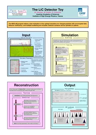
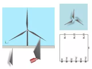
This document discusses the principles of lift and drag in wind turbine rotor blades, employing equations that define these forces based on angle of attack and several operational parameters. It details the implementation of control structures for pitch management, ensuring blades operate within a stable region to maximize efficiency and safety. The system also includes yaw control to maintain optimal turbine alignment with wind. Important calculations are highlighted, including the effects of pure wind, rotation speed, and torque commands on performance.

E N D
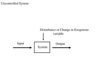
B A Output(Force) x Input(Valve Displacement) Tank Pump
S1 S2 S3
Calculating Blade Loads Lift= 0.5*v2*Area*ρ*CL Drag= 0.5*v2*Area*ρ*CD Where CL&CD= f(Angle ofAttack) Lift Drag Rotation Wind = Rotor Speed(ω)*radius Positive Pitch Angle (θ) InflowAngle Pure Wind(Vinf) α ResultantWind Angle ofAttack(α) InflowAngle PitchAngle = - Pure Wind Rotation Wind = atan
ControlStructureforPitchControl ControlStructureforPitchControl Pitch AngleCommand ValvePosition Desired AngleofAttack DesiredRotor Speed + Control Control - InflowAngle ActualRotor Speed Limit PitchtoStable Region
ControlStructurefor Yaw Control ControlStructurefor Yaw Control Yaw RateCommand TorqueCommand YawCommand Control Control Limit Rateto 0.5 deg/s Nacelle Yaw Angle Nacelle Yaw Rate
Pitch Wind Blades Geartrain Generator Hub Yaw Tower Grid