HiperLAN2 Protocol Stack for Data Transfer
Learn about the channels, protocols, and structure of the HiperLAN2 network for efficient data transfer. Explore logical channels and convergence layers.

HiperLAN2 Protocol Stack for Data Transfer
E N D
Presentation Transcript
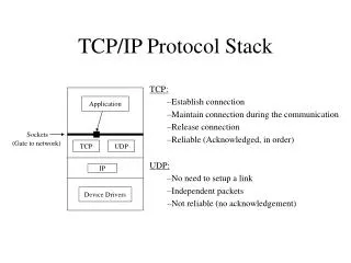
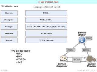
2. DLC layer HiperLAN2 defines six different so-called transport channels for data transfer Broadcast channel (BCH) - 15 bytes Frame channel (FCH) - 27 bytes Access feedback channel (ACH) - 9 bytes Long transport channel (LCH) - 54 bytes Short transport channel (SCH) - 9 bytes Random channel (RCH) - 9 bytes
The following logical channels are defined in HiperLAN2 1. Broadcast control channel (BCCH): This channel on the downlink conveys a constant amount of broadcast information concerning the whole radio cell. 2. Frame control channel (FCCH): The FCCH describes the structure of the remaining parts of the MAC frame. 3. Random access feedback channel (RFCH): This channel informs MTs that have used an RCH in the previous frame about the success of their access attempt. 4. RLC broadcast channel (RBCH): This channel transfers information regarding RLC control information, MAC IDs during an association phase. 5. Dedicated control channel (DCCH): This channel carries RLC messages related to a certain MT and is established during the association of an MT.
6. User broadcast channel (UBCH): A UBCH transfers broadcast messages from the convergence layer. 7. User multi-cast channel (UMCH): This channel performs unacknowledged transmission of data to a group of MTs. 8. User data channel (UDCH): Point-to-point data between an AP and an MT (CM) or between two MTs (DM) use this channel. 9. Link control channel (LCCH): This bi-directional channel conveys ARQ feedback and discards messages between the error control functions of an AP and an MT (CM) or between two MTs (DM). 10. Association control channel (ASCH): This channel is only used in the uplink and for currently non-associated MTs (related to a certain AP).
3. Convergence layer • As the physical layer and the data link layer are independent of specific core network protocols, a special convergence layer (CL)is needed to adapt to the specific features of these network protocols. • HiperLAN2 supports two different types of CLs: cell-based and packet-based. • The cell-based CL expects data packets of fixed size, while the packet-based CL handles packets that are variable in size. • Three examples of convergence layers follow • Ethernet • IEEE 1394 ( Firewire ) • ATM
Bluetooth • Bluetooth technology discussed here aims at so-called ad-hoc piconets, which are local area networks with a very limited coverage and without the need for an infrastructure. • This is a different type of network is needed to connect different small devices in close proximity (about 10 m) without expensive wiring or the need for a wireless infrastructure. • The envisaged gross data rate is 1 Mbit/s, asynchronous (data) and synchronous (voice) services should be available. • Like IEEE 802.11b, Bluetooth operates in the 2.4 GHz ISM band.
2. Architecture • Networking • Bluetooth operates on 79 channels in the 2.4 GHz band with 1 MHz carrier spacing. • Each device performs frequency hopping with 1,600 hops/s in a pseudo random fashion. • Bluetooth applies FHSS for interference mitigation. • A piconetis a collection of Bluetooth devices which are synchronized to the same hopping sequence. • One device in the piconet can act as master(M), all other devices connected to the master must act as slaves(S). • The master determines the hopping pattern in the piconetand the slaves have to synchronize to this pattern. • Each piconet has a unique hopping pattern.
parked devices (P) can not actively participate in the piconet (i.e., they do not have a connection), but are known and can be reactivated within some milliseconds. • Devices in stand-by (SB) do not participate in the piconet. • Each piconethas exactly one master and up to seven simultaneous slaves. More than 200 devices can be parked. • The reason for the upper limit of eight active devices, is the 3-bit address used in Bluetooth. • All active devices are assigned a 3-bit active member address(AMA). All parked devices use an 8-bit parked member address(PMA). Devices in stand-by do not need an address. • The idea of forming groups of piconets called scatternet. • Bluetooth applies FH-CDMA for separation of piconets.
Protocol stack • The Bluetooth protocol stack can be divided into a core specification and profile specifications. • The core protocols of Bluetooth comprise the following elements: 1. Radio: Specification of the air interface, i.e., frequencies, modulation, and transmit power. 2. Baseband: Description of basic connection establishment, packet formats, timing, and basic QoS parameters. 3. Link manager protocol: Link set-up and management between devices including security functions and parameter negotiation. 4. Logical link control and adaptation protocol (L2CAP): Adaptation of higher layers to the baseband. 5. Service discovery protocol: Device discovery in close proximity plus querying of service characteristics .
RFCOMM supports multiple serial ports over a single physical channel. • The telephony control protocol specification – binary(TCS BIN) describes a bit-oriented protocol that defines call control signaling for the establishment of voice and data calls between Bluetooth devices. • The host controller interface(HCI) between the baseband and L2CAP provides a command interface to the baseband controller and link manager, and access to the hardware status and control registers.
3. Radio layer • Bluetooth uses the license-free frequency band at 2.4 GHz allowing for worldwide operation with some minor adaptations to national restrictions. • A frequency- hopping/time-division duplex scheme is used for transmission, with a fast hopping rate of 1,600 hops per second. • Bluetooth transceivers use Gaussian FSK for modulation and are available in three classes: • Power class 1: Maximum power is 100 mW and minimum is 1 mW (typ. 100 m range without obstacles). Power control is mandatory. • Power class 2: Maximum power is 2.5 mW, nominal power is 1 mW, and minimum power is 0.25 mW (typ. 10 m range without obstacles). Power control is optional. • Power class 3: Maximum power is 1 mW.
Physical links Bluetooth offers two different types of links, a synchronous connection-oriented link and an asynchronous connectionless link
5. Link manager protocol • The following groups of functions are covered by the LMP: • Authentication, pairing, and encryption • Synchronization • Capability negotiation • Quality of service negotiation • Power control • Link supervision • State and transmission mode change Sniff state: It has the highest power consumption of the low power states. Hold state: The device does not release its AMA but stops ACL transmission. Park state: In this state the device has the lowest duty cycle and the lowest power consumption.
6. L2CAP • The logical link control and adaptation protocol (L2CAP) is a data link control protocol on top of the baseband layer offering logical channels between Bluetooth devices with QoS properties. • L2CAP is available for ACLs only. • Audio applications using SCOs have to use the baseband layer directly. • L2CAP provides three different types of logical channels that are transported via the ACL between master and slave: • Connectionless: These unidirectional channels are typically used for broadcasts from a master to its slave(s). • Connection-oriented: Each channel of this type is bi-directional and supports QoS flow specifications for each direction. • Signaling: This third type of logical channel is used to exchanging signaling messages between L2CAP entities.
8. SDP • To find new services, Bluetooth defined the service discovery protocol (SDP). • SDP defines only the discovery of services, not their usage. Discovered services can be cached and gradual discovery is possible. • Devices that want to offer a service have to install an SDP server. For all other devices an SDP client is sufficient. • All the information an SDP server has about a service is contained in a service record. • A service attribute consists of an attribute ID and an attribute value. The 16-bit attribute ID distinguishes each service attribute from other service attributes within a service record.
9. Profiles • To provide compatibility among the devices offering the same services, Bluetooth specified many profiles in addition to the core protocols. • Profiles represent default solutions for a certain usage model. They use a selection of protocols and parameter set to form a basis for interoperability. • The following basic profiles have been specified: Generic access, service discovery, cordless telephony, intercom, serial port, headset, dialup networking, fax, LAN access, generic object exchange, object push, file transfer, and synchronization. Additional profiles are: advanced audio distribution, PAN, audio video remote control, basic printing, basic imaging, extended service discovery, generic audio video distribution, hands-free, and hardcopy cable replacement. Each profile selects a set of protocols.
Mobile IP 1. Goals, assumptions and requirements 2. Entities and terminology 3. IP packet delivery 4. Agent discovery 5. Registration 6. Tunneling and encapsulation 7. Optimizations 8. Reverse tunneling 9. IPv6 10. IP micro-mobility support
Many protocols and mechanisms developed for the network layer to support mobility. The most prominent example is Mobile IP, which adds mobility support to the internet network layer protocol IP. • While systems like GSM have been designed with mobility in mind, the internet started at a time when no one had thought of mobile computers. • Today’s internet lacks any mechanisms to support users traveling around the world. IP is the common base for thousands of applications and runs over dozens of different networks. • This is the reason for supporting mobility at the IP layer; mobile phone systems, for example, cannot offer this type of mobility for heterogeneous networks. • To merge the world of mobile phones with the internet and to support mobility in the small more efficiently, so-called micro mobility protocols have been developed. • Another kind of mobility, portability of equipment, is supported by the dynamic host configuration protocol (DHCP)
1. Goals, assumptions and requirements • A host sends an IP packet with the header containing a destination address with other fields. The destination address not only determines the receiver of the packet, but also the physical subnet of the receiver. • For example, the destination address 129.13.42.99 shows that the receiver must be connected to the physical subnet with the network prefix 129.13.42. • Routers in the internet now look at the destination addresses of incoming packets and forward them according to internal look-up tables. • As long as the receiver can be reached within its physical subnet, it gets the packets; as soon as it moves outside the subnet, a packet will not reach it. 1.1 Quick ‘solutions’ • A host needs a so-called topologically correct address. • Another approach is the creation of specific routes to the mobile node. 1.2 Requirements i. Compatibility ii. Transparency iii. Scalability and efficiency iv. Security