Download
1 / 29
1.93k likes | 6.64k Views
Design of a Vertical-Axis Wind Turbine. MUN VAWT DESIGN. Group 11 Jonathan Clarke Luke Hancox Daniel MacKenzie Matthew Whelan. Agenda. Phase 1 Project Goals & VAWT Benefits Configuration Design Selection Phase 2 & 3 Aerodynamic Analysis Structural Analysis Mechanical Components

E N D
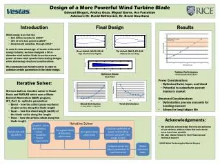
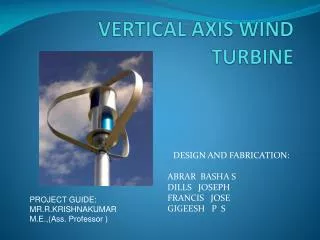
Design of a Vertical-Axis Wind Turbine MUN VAWT DESIGN Group 11 Jonathan Clarke Luke Hancox Daniel MacKenzie Matthew Whelan
Agenda • Phase 1 • Project Goals & VAWT Benefits • Configuration • Design Selection • Phase 2 & 3 • Aerodynamic Analysis • Structural Analysis • Mechanical Components • Economic Analysis Image Credits: The Telegram
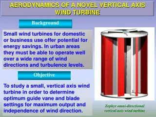
Problem Definition and Goals • Problem Definition • Design a VAWT for operation in remote communities in Newfoundland and Labrador. • The turbine should: • Work in conjunction with diesel generators • Simple design to reduce manufacturing costs and maintenance issues • Produce at least 100 kW of power at rated wind speed • Able to account for variable wind conditions in the target area
Project Scope • The project will examine the following aspects of the VAWT design: • Detailed structural design and analysis • Detailed aerodynamic simulation using computational fluid dynamics • Basic vibrational analysis • Modelling and engineering drawings of mechanical and structural components • Economic analysis
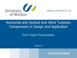
Why a Vertical Axis Wind Turbine? • Heavy drivetrain components are located at the base • Easier to maintain • They operate from winds in any direction • No yaw system required • Generate less noise than horizontal-axis turbines
Concept Selection: VAWT Configurations Two main configurations: Savonius and Darrieus • Savonius is drag driven • Low efficiency • Darrieus is lift driven • High efficiency
Concept Selection: VAWT Configurations X Two main configurations: Savonius and Darrieus • Savonius is drag driven • Low efficiency • Darrieus is lift driven • High efficiency
Concept Selection: Darrieus Configurations Simple Less Efficient Complex More Efficient H-Rotor Full Darrieus Helical
Concept Selection: Darrieus Configurations Simple Less Efficient Complex More Efficient H-Rotor Full Darrieus Helical
Concept Selection: Airfoil Profiles • Extra thickness – increases blade strength • Higher CL,Max for positive angles of attack
Concept Selection: Number of Blades • Capital Cost • Symmetrical Loading • Torque Ripple
Concept Selection: Number of Blades • Capitol Cost • Symmetrical Loading • Torque Ripple 3 Bladed
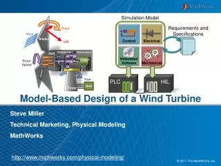
Aerodynamic Design W/m2 = ½ ρavg cP V3 • Preliminary sizing: 320 m2 swept area • From wind power density formula: • Analytical analysis using QBlade • Developed torque and power curve • Validation using lift & drag equations • Validation using ANSYS CFX Sizing Validation Fl = ½ ρavg A cl W2
QBlade Results Rated Power: 100 kW @ 40 km/h Max Power: 130 kW @ 50 km/h Cut-Out Speed: 94 km/h Cut-In Speed: 7 km/h
ANSYS CFX Setup • Used 2D simulation • Sacrifices some accuracy for reduced computational demand • Sufficient to validate QBlade results • Fine mesh near airfoils to capture boundary layer effects • Mesh refinement study carried out
ANSYS CFX Results • Average power: 145 kW at peak operating condition • Does not account for blade tip losses • Sufficient to validate QBlade results
Dynamic Model • Suitable under variable wind conditions
Structural Design • Composite Blade Design • E-Glass Fibre and Epoxy • Hollow Square Shape • Wall Thickness: 50 mm • Length: 20 m • Fibreglass Layers: 386 • Strut Design • Hollow Cylindrical Shaft • AISI 1045 Cold Drawn Steel • Outer Diameter: 36 cm • Inner Diameter: 28 cm • Length: 7.6 m
Structural Design • Hub Column Design • AISI 1045 Cold Drawn Steel • Outer Diameter: 0.6 m • Inner Diameter: 0.55 m • Length: 8.5 m • Tower Design • A35 Structural Steel • 8 meter lengths • Outer Diameter: 3 m • Inner Diameter: 2.95 m
Vibrations • At 40 RPM, the aerodynamic and centripetal forces alternate 3 times / cycle • Operating Frequency (@ 40 RPM) = 2 Hz • Maximum Vortex Shedding Frequency = 1.3 Hz
Vibrations Struts Blades Tower
Mechanical Components • Drive Shaft • Outer Diameter: 406.4 mm • Inner Diameter: 355.6 mm • Length: 7 m • Bearings • Tapered Roller Bearing • Bore: 406.4 mm • Outer Diameter: 546.1 mm • Life Span: >20 years • Mechanical Coupling • RB Flexible Coupling
Braking and Control • Dynamic braking used to control speed in high winds • Dissipates excess power through a network of resistors • External-contact drum brakes used for shutdown • Spring-applied, electrically released • Fail-safe operation • Compressed air starting system • Cheap and reliable SIBRE Siegerland Bremsen GmbH
Generator • Low-speed permanent-magnet generator • Eliminates need for a gearbox • Units are typically custom-built for specific applications • Rated speed can be as low as 10 rev/min Sicme Motori Srl
Economic Analysis $ • Estimated Capital Cost • $425 000.00 • Quotes • Maintenance Cost per year • VAWT Turbine - $10 000.00 • Diesel Generators - $86 380.00 • Projected Fuel Cost of 2015 • $3 630 967.00 • Payoff Period • ~1M dollars saved annually for an installation of 5 turbines • 3 Years
Future Work • Full 3D CFD analysis • Structural Dynamic Model • Foundation / Civil Work • Control System Design • Full Scale Testing
Conclusion • Goal: Design a simple, robust vertical-axis wind turbine for use in remote communities • Project goals were met • VAWT design is a viable option to provide power to remote communities
MUN VAWT DESIGN ENGI 8926 Mechanical Design Project II QUESTIONS? http://www.munvawtdesign.weebly.com Acknowledgements: Thank you to Dr. Sam Nakhla for guidance on structural analysis.