Planning based on Model Checking
Dept. of Information Systems and Applied CS Bamberg University. Planning based on Model Checking. Seminar Paper. Svetlana Balinova. Outline. 1. Introduction 2. Explicit Model Checking 3. Temporal Logic 4. Symbolic Model Checking

Planning based on Model Checking
E N D
Presentation Transcript
Dept. of Information Systems and Applied CS Bamberg University Planning based on Model Checking Seminar Paper Svetlana Balinova
Outline 1. Introduction 2. Explicit Model Checking 3. Temporal Logic 4. Symbolic Model Checking 5. Binary Decision Diagrams 6. Planning for Reachability Goals
1.Introduction „Model Checking is an automatic technique for verifying correctness properties of safety-critical reactive systems “ 2 kinds of correctness properties: Safety Liveness Classical planning Planning under uncertainty Determinism Nondeterminsm Full observability Partial observability Reachability goals Extended Goals
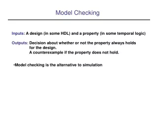
2.Explicit Model Checking State space: a system, implemented as Kripke Structure Verification: build a computation tree for all possible paths within a System
2.Explicit Model Checking Warning system for planes green signal signal, evasion recommendation
3.Temporal Logic Properties to be checked must be formalized in a temporal logic. A temporal logic provides operators which represent time dependences. Operators: F (in the future), X (next time), G (globaly) Path quantifiers: A (always), E (exist) CTL (Computation Tree Logic) – branching time. LTL (Linear-Time Temporal Logic) – linear time. Validity of LTL and CTL formulas: Model Checking Algorithms.
3.Temporal Logic Examples: CTL formula: AX φ φ φ ……………………. …….. LTL formula: F φ φ
4. Symbolic Model Checking Faces the state explosion problem of explicit state Model Checking. Exploring sets of states, rather than single states. In order to represent a model checking problem symbolically, we need to represent symbolically: the sets of states of a Kripke Structure, its transition relation, and the model checking algorithms.
4. Symbolic Model Checking Symbolic Representation of Sets of States: A vector x of Boolean variables where each variable corresponds to a an atomic propostion in P. x = { green, signal, evasiion recommendation} A state s is represented with a formula ξ(s) on the propositions: ξ(so) = green, ¬signal, ¬evasion recommendation ξ(s1) = ¬green, signal, ¬evasion recommendation ξ(s2) = ¬green, signal, evasion recommendation A set of states Q S represented symbolically as:
4. Symbolic Model Checking Symbolic Representation of Transition Relations A vector of state variables x = <x1, ......, xn>and a further vector of next state variables x‘ = <x‘1, ......, x‘n> x‘ = { green’, signal’, evasion recommendation’} A transition ξ(< so, s1 >) encoded as: ξ(< so, s1 >) = ξ(< so >) , ξ‘(< s1 >) ξ(< so, s1 >) = (green, ¬signal, ¬evasion recommendation), (¬green‘, signal’, ¬evasion recommendation’) Transition relation R represented symbolically as: ξ(R) = Vξ(r)ξ(R) = Vξ(r) r є R
4. Symbolic Model Checking Symbolic Representation of Model Checking Algorithms Replace each function call with the symbolic counterpart. Cast the operations on sets into the corresponding operations on propositional formulas.
5.Binary Decision Diagrams An efficient approach for manipulation of Boolean formualas. Abinary decision diagram represents a Boolean function as rooted, directed acyclic graph. Each nonterminal vertex v is labeled by a variable var(v) and has ars directed toward two children: lo(v) and hi(v). In the first case the variable is assigned 0(- - -) and in the second 1( ). Each terminal vertex is labeled 0 or 1 ABoolean function may be represented by a truth table, binary decision tree etc. A tree is said to be ordered if the variables always occur in the same order along any path from root to leaf.
5.Binary Decision Diagrams Example: Truth Table and Decision Tree Representations of a Boolean Function. A dashed (solid) tree branch denotes the case where the decision variable is 0 (1).
5.Binary Decision Diagrams Reduction of decision tree to OBDD 1. Remove Duplicate Terminals: Eliminate all but one terminal vertex with a given label and redirect all arcs into the eliminated vertices to the remaining one. 2. Remove Duplicate Nonterminals: If nonterminal vertices u and v have var(u)=var(v), lo(u)=lo(v), and hi(u)=hi(v), then eliminate one of the two vertices and redirect all incoming arcs to the other vertex. 3. Remove Redundant Tests: If nonterminal vertex v has lo(v)=hi(v), then eliminate v and redirect all incoming arcs to lo(v).
5.Binary Decision Diagrams Applying the three reduction rules to the tree of the last example yields the canonical representation of the function as an OBDD.
6. Planning for Reachability Goals • Rechability goals: Goals are sets of states, i.e., the objective is to • build a plan that leads to one of the goal states. • A planning domain is a nondeterministic state-transition system Σ= (S, A, ), where: S is a finite set of states A is a finite set of actions : S A 2sis the state-transition function.
6. Planning for Reachability Goals Example: nondeteministic state-transition system for a simplified DWR (dock-worker-robots) domain
6. Planning for Reachability Goals A plan is a policy, i.e. a function that maps states into actions. A policy π for a planning domain Σ= (S, A, ) is a set of pairs (s, a) such that (s, a) є A(s). Policies for the domain in the previous examle: π1 = {(s1, move(r1,l1,l2)), (s2, move(r1,l2,l3)), (s3, move(r1,l3,l4))} π2 = {(s1, move(r1,l1,l2)), (s2, move(r1,l2,l3)), (s3, move(r1,l3,l4)), (s5, move(r1,l3,l4))} π3 = {(s1, move(r1,l1,l4))}
6. Planning for Reachability Goals We represent the execution of a policy in a planning domain with an execution structure, i.e., a directed graph in which the nodes are all of the states of the domain that can be reached by executing actions in the policy, and the arcs represent possible state transitions caused by actions in the policy. π1 π2 π3
6. Planning for Reachability Goals A planning problem is a triple (Σ, So, Sg), where Σ= (S, A, ) is a planning domain, So S is a set of initial states, and Sg S is a set of goal states. Types of solutions for a planning problem: weak solutions strong solutions strong cyclic solutions Planning algorithms – designed to work on sets of states, thus taking advantage of the BDD-based symbolic Model Checking.