Download
1 / 34
380 likes | 623 Views
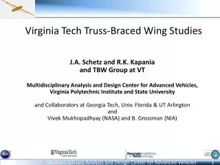
Virginia Tech Truss-Braced Wing Studies. J.A. Schetz and R.K. Kapania and TBW Group at VT Multidisciplinary Analysis and Design Center for Advanced Vehicles, Virginia Polytechnic Institute and State University and Collaborators at Georgia Tech, Univ. Florida & UT Arlington and

E N D
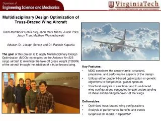
Virginia Tech Truss-Braced Wing Studies J.A. Schetz and R.K. Kapania and TBW Group at VT Multidisciplinary Analysis and Design Center for Advanced Vehicles, Virginia Polytechnic Institute and State University and Collaborators at Georgia Tech, Univ. Florida & UT Arlington and Vivek Mukhopadhyay (NASA) and B. Grossman (NIA) 1
Goal of the Research Use Multidisciplinary Design Optimization (MDO) to explore the potential for large improvements in long- and medium-range transonic, transport aircraft performance by employing truss-braced wings (TBW)combined with other synergistic advanced technologies. Ground Rules for VT Studies: Mach 0.85 cruise All-metal airplanes GE90 type engines Focus on truss benefits
Original Pfenninger Vision Fuselage profile For low wetted area Wing tip for vortex control Large span wing to reduce induced drag Optimized truss support to reduce wing weight- Reduce interference drag Thin wing at root for laminar flow Pfenninger, W., “Laminar Flow Control Laminarization,” AGARD Report 654, “Special Course on Concepts for Drag Reduction” , 1977
Main Mission (“777 ER”) Ma c h 0.85 Cr u i se Ma c h 0.85 140 K not s C l i mb Ap p ro a ch Sp e ed 350 NM I 773 0 N MI R ange 11,0 0 0 F T 11,0 0 0 F T L DG R e s er v e R ange T /O Fi eld L e ngth F ie l d Lengt h • Use MDO to design 305-passenger, 7730 nmi range, Mach 0.85 transport aircraft of Cantilever, Strut-Braced-Wing (SBW), and Truss-Braced Wing (TBW) configurations
MDO Design Environment Baseline Design Design Environment N^2 Diagram ModelCenter Environment Design Environment Block Diagram Parametric Geometry Propulsion Aerodynamics Optimizer Fuel Loading TOGW Convergence Structural Optimization Performance, Cost Function, Constraints Weight Estimation
Propulsion Model M=0.85 • Dimensions and weights • Simplified VT model similar to Mattingly Elements of Propulsion: Gas Turbines And Rockets • Performance: 1. Simplified model 2.NASA fixed deck • “GE-90-like” 3.NPSS or Reduced-order NPSS from GT
Aerodynamic Model • Calculates: • Aerodynamic drag • Aerodynamic loading (input for structural design module) • Drag breakdown models: • Induced drag based on Trefftz plane model • Friction/Profile drag based on semi-empirical methods • Wave drag based on the Korn Equation • Interference drag based on literature and response surfaces from offline CFD
Structural Design Requirements • Total of 17 cases: • 2.5 g 100% / 50% fuel • -1 g 100% / 50% fuel • 2 g taxi bump • 12 gust cases, 50% 100% fuel, various altitudes • Motivated by low wing loading MDO designs • Simplified discrete gust modeling • Using gust alleviation factor • Designs evaluated for flutter performance post MDO Vc FlutterEnvelope Altitude (x103ft) Mach
Structural Design Methodology z t1=(t/c) ·c/2 t2 t0 B A x C D cst Offline RSM generationLatin-Hypercube SamplingKriging Surrogate Model Design Variables Wing Structural Weight Estimation Evaluate Response Surface Response Surface Model Wing Weight • Estimation of load carrying structural weight • Bending and shear material • Structural optimization • Finite element analysis • Stress, displacement and buckling constraints • Flutter constraints with geometric stiffness influence • Structural response surface model used in MDO
TBW Weight Estimation • Detailed physics based wing system structural weight estimation • In-house tool optimizes for bending and shear material weight • Other components: • FLOPS: secondary weight • Folding wing penalty • Fuselage pressurization penalty
Performance Constraints Range ≥ 7730 [NM] + 350 [NM] (reserve) Initial Cruise ROC ≥ 500 [ft/min] Max. cl (2-D) ≤ 0.8 Available fuel volume ≥ required fuel volume 2nd segment climb gradient (TO) ≥ 2.4% (FAR) Missed approach climb gradient ≥ 2.1% (FAR) Approach velocity ≤ 132.5 [kn.] Balanced field length (TO & Land.) ≤ 11,000 [ft] Cruise altitude ≤ 48,000 [ft]
Truss Topology Optimization Study • Triangular Loading • Two-dimensional analysis • Buckling not included • Single load case 15% Volume Fraction Fewer Members Larger tip deflection Larger strain energy • All designs with same volume fraction have same mass
Muldisciplinary Design Optimization Study • Cost functions: Minimum fuel/emissions and TOGW • Configurations • Cantilever • Strut-Braced wing (SBW) • Single Jury TBW • 2-Jury TBW • 3-Jury TBW • Aggressive laminar flow • Aggressive junction fairing • Fuselage riblets
Minimum Fuel/Emissions Design Study Active Constraints range, deflection range, fuel range,clmax range,clmax, Vapproach range,clmax, Vapproach
+80% Minimum Fuel/Emissions Design Study +160% B777: 20 +70% B777: 10 +11% B777: 512 B777: 183 B777: 71 B777: 106 -8% -33%
Minimum TOGW Design Study Active Constraints range, initial cruise rate of climb, fuel range, balanced field length, Vapproach range range range, initial cruise rate of climb, Vapproach, clmax
+80% Minimum TOGW Design Study B777: 10 +50% +40% B777: 20 B777: 183 B777: 512 B777: 106 B777: 71 -17% -26% -10%
Comparison of Designs: Min. Fuel and Min. TOGW B777: 106 B777: 512 B777: 183 B777: 20 B777: 10 B777: 71
1-Jury TBW Configurations Minimum Fuel/Emissions Minimum TOGW
MDO Configurations: Drag Breakdown Minimum Fuel Minimum TOGW • All minimum fuel configurations cruise altitude is between 46,000 to 48,000 ft • Increasing number of members reduces induced drag and increases profile drag • Additional surface area from more members reduces system benefit • Fuselage drag reduction is needed.
Flutter Boundary of TBW Airplane Designs Minimum Fuel Minimum TOGW 3-Jury SBW 3-Jury 2-Jury 1-Jury SBW 2-Jury 1-Jury Vc Altitude (x103ft) Altitude (x103ft) Vc FlutterEnvelope FlutterEnvelope Mach Mach Flutter Mach numbers for 100% fuel at 2.5g pull-up maneuver • Flutter margin reduces with increasing number of members due to higher span • Passive and active control measures under investigation • Passive methods • Ballast mass • TBW geometry modification: parametric study • Aeroservoelasticity
Flutter Ballast Mass Study: Ballast Mass is 2% of Wing Mass SBW Flutter speed: VF=588 fps, MF=0.526; 600 lb Ballast mass Best improvement of 1.1% with mass at 36% span, 98% chord Very low sensitivity to ballast mass location
Flutter Ballast Mass Study: Ballast Mass from 2% to 8% Very low sensitivity to size and location of ballast mass
Truss-Braced Wing Geometry Parametric Study Influence of selected geometric parameters on aeroelastic performance of TBW Strut-sweep (ΛS), Wing-strut span intersection (η) SBW, TBW 1-jury, TBW 2-jury, TBW 3-jury Same cross-sectional dimensions for each configuration Chord, t/c ratio Values correspond to TBW 1-jury configuration (from MDO) Each configuration sized for same requirements
Comparison of TBW Configurations (η=55%, b/2=175 ft, ΛW=10°) Addition of jury strut members Reduces wing weight Largest reduction (21%) from SBW to TBW 1-jury TBW configurations have similar flutter boundary Low sensitivity to strut-sweep TBW 1-jury and 2-jury offer 19% increment in flutter boundary with 14% higher weight TBW 3-jury offers 49% increment in flutter boundary with 20% higher weight
Comparison of TBW Configurations (η=70%, b/2=175 ft, ΛW=10°) Addition of jury strut members Reduces wing weight Largest reduction (14%) from SBW to TBW 1-jury TBW configurations show strong sensitivity to strut-sweep Significant flutter boundary increment from SBW TBW 1-jury and 2-jury have similar weight and flutter boundary 33% increment in flutter boundary with 20% higher weight TBW 3-jury offers 75% increment in flutter boundary with 8% higher weight
Conclusions and Future Work • TBW airplane configurations offer significant performance benefits • Higher span increases weight and reduces flutter speed • Outboard wing-strut intersection location • Increases wing weight in present study due to active buckling • Increases flutter speed for TBW configurations • Larger difference in wing- & strut-sweep could be used to help flutter performance • Flutter speed sensitivity to strut-sweep increases with spanwise intersection location • Airplane MDO would show multidisciplinary influence • Large benefit in wing weight reduction and flutter boundary increment from SBW and TBW configurations • TBW 3-jury offers highest benefit in flutter performance • Ongoing efforts and future work • Active control techniques • Body-freedom flutter and nonlinear aeroelasticity
+80% Minimum Fuel/Emissions Design Study +160% B777: 20 +70% B777: 10 +18% +11% B777: 4340 B777: 512 B777: 183 B777: 71 B777: 106 -8% -33%
+80% Minimum TOGW Design Study B777: 10 +12% +80% +40% B777: 20 B777: 4340 B777: 183 B777: 512 B777: 106 B777: 71 -17% -26% -10%
Comparison of Designs: Min. Fuel and Min. TOGW B777: 4340 B777: 106 B777: 512 B777: 183 B777: 20 B777: 10 B777: 71
Minimum Fuel/Emissions Design: 1-Jury TBW Buckling and Flutter Mode Shapes Buckling Mode: 2g taxi-bump Buckling factor = 1.0 Buckling Mode: 2.5g pull up Buckling factor = 1.8 • Global wing buckling mode for 2.5g pull-up • Strut buckling mode for 2g taxi-bump • Flutter mode: combination of 3 modes: two bending + torsion Flutter Mode: 2.5g, 100% fuel, Sea-level Vf = 300 fps, 1.7 Hz, reduced freq. = 0.32