Download
1 / 12
120 likes | 288 Views
Journal Club. Jan 2012. Hollow-fibre – coupling. EH 11. EH 12. Different modes propagate in the fibre. EH 13. EH 14. Nisoli , M. et al; Selected Topics in Quantum Electronics, IEEE Journal of. 1998 , 4, 414-420. Hollow-fibre – mode discrimination / attenuation. Different fibre radii.

E N D
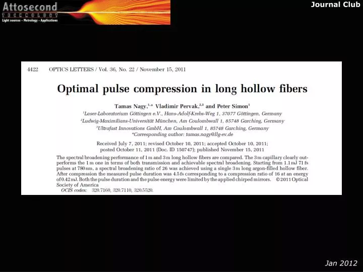
Journal Club Jan 2012
Hollow-fibre – coupling EH11 EH12 Different modes propagate in the fibre EH13 EH14 Nisoli, M. et al; Selected Topics in Quantum Electronics, IEEE Journal of. 1998, 4, 414-420.
Hollow-fibre – mode discrimination / attenuation Different fibre radii Different modes small fibre radius => high intensity but low transmission long fibre => good mode discrimination but lower transmission
Hollow fibre – design considerations P limited by self-focusing ionizaton limits minimal core radius length of fiber is limited by propagation losses amin (Ar) = 1.6 amin (Ne) = 1.8 amin (He) He α ~ 0.45, β ~ 0.51 Vozzi, C. et al., 2005. Applied Physics B: Lasers and Optics, 80(3), pp.285-289
conventional Hollow fibre parameters in principle: larger inner diameter and using a longer fiber to compensate for smaller intensity allows for better overall transmission Input: ~1 mJ with τ~30 fs best compromise between transmission losses and broadening. L is limited by production and table. Transmission sensitive to radius (more bendy = less transmission) • L = 1 m • ID = 250 µm Nagy, T., Forster, M. & Simon, P., 2008 Appl. Opt., 47(18), pp.3264-3268.
Flexible fiber – why? bending problem is eliminated by stretching the fibre on the ends. Nagy, T., Forster, M. & Simon, P., 2008 Appl. Opt., 47(18), pp.3264-3268.
Flexible fibers – what is this? ID/OD = 250µm / 360µm ID/OD = 320µm / 440µm
Flexible hollow fibers – setup “After curing, the fiber is cut within the glued regions by a diamond tool.” HF: hollow fiber GT: glass tube VC: vacuum-tight cement OR: O-ring CR: clamping ring VT: vacuum tubing
Flexible fibers – Results input: 1.1mJ, 70fs, 780nm 42% 1m 250µm Ar 300 mbar static fill F=9.2 a lot less then with no gas evacuated!! (=useless) 64% 3m 320µm Ar 200 mbar static fill F = 9.7 close to evacuated spot too small for 300 mbar of Argon? ionization at entrance? shifting of z-position? Obviously you put more effort into result you want to see Can you get better transmission with 1m? F = Δωout/Δωin
Flexible fibers – Results “The ultimate spectral broadening with still regular spectral shape and acceptable spatial homogeneity” 36% 1m 250µm Ar 500 mbar static fill 48% 3m 320µm Ar 500 mbar static fill
Flexible fibers – Results FROG says: 4.5 fs with 12µm (θ = 30.8°) BBO!! 48% 3m 320µm Ar 500 mbar
Discussion Pros: easy to keep the fiber straight fibers don’t break that easily good transmission good beam profile after fiber Cons: increasing ID => longer tubes table size limited tiny fiber might be immediatly burnt at higher energies larger ID impractical for us?