Pre-Alignment Strategies for Component Positioning in Coordinate Systems
140 likes | 262 Views
This document discusses strategies and solutions for the pre-alignment of components in a coordinate system, including determining component positions, reviewing solutions, and feasibility strategies. Various network systems and alignment methods are explored to achieve accurate component positioning. The text outlines different solutions, challenges, and technologies involved in pre-alignment and repositioning processes.

Pre-Alignment Strategies for Component Positioning in Coordinate Systems
E N D
Presentation Transcript
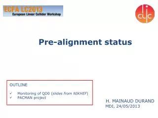
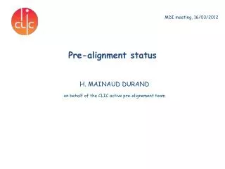
PRE-ALIGNMENT for CDR CTC meeting Hélène MAINAUD DURAND, BE/ABP/SU, 06/04/2010
Determination of the position of the components in a general coordinate system Outline = Pre-alignment + Repositioning • Determination of the position of the components • Review of the possible solutions • Strategy towards the feasibility • General concept of re-positioning • Baseline • Strategy towards the feasibility • Special case of the Final Focus • Conclusion • Proposed pre-alignment solution for CDR • Studies for the TDR
Determination of the position of the components Geodetic Reference Network (GRN) Metrologic Reference Network (MRN) Support Pre-alignment Network (SPN) Alignment and fiducialisation of each component on the supports (AFC)
No solution answering the requirements exists yet! Status of the different solutions Metrologic Reference Network (MRN) • Stretched wire, modelized in vertical with HLS system • Long range RASCLIC (NIKHEF) • Multi-point alignment system based on laser beam. Support Pre-alignment Network (SPN) • Stretched wire • RASNIK, short range RASCLIC (NIKHEF) • Multi-point alignment system based on laser beam. Alignment and fiducialisation of each component on the supports (AFC)
Status of the different solutions Pre-alignment solutions from NIKHEF RASCLIC RASNIK • Drawbacks: • Vacuum flanges on long distances (replaced by helium flushing) • 3 point alignment system because of non regular distances along main linac, the creation of sub-network is needed. • Not easy at all to establish a formal collaboration with NIKHEF
Status of the different solutions Laser Alignment Multipoint Based- Design approach (LAMBDA) • Technical note concerning the concept proposal in progress • Preliminary study concerning the mechanical shutters will start soon • Definition of the subject for a doctorate student in progress
Status of the different solutions Stretched wire solution • Concept of MRN to be validated in the TT1 facility
Status of the different solutions Stretched wire solution • Two types of WPS
Status of the different solutions Strategy towards the feasibility • Only one solution ready for CDR : stretched wire + WPS • It is not mandatory to define the technology concerning the WPS now • cWPS: • design of a new mechanical interface and associated calibration bench improve the accuracy (target : accuracy < 5 μm) • cost study to be launched for 50 000 units. • oWPS: • definition of the next generation under progress • Several studies launched to address the drawbacks of the WPS and stretched wire • Development of a concept allowing to stretch a wire without access to the sensors and the wire protection • A method was found to stretch two wires in the same optical sensor (to be validated on long distance) • Test of a concept to modelize the wire measuring its frequency • Determination of the local deviation of vertical (so to have a perfect knowledge of the geoïd)
Repositioning Baseline MB Quad DB and MB girders Hypotheses • Motorized displacements along 5 DOF • Range ± 3 mm • Resolution: 0.5 micron • Motorized displacements along 3 DOF • Range ± 3 mm • Resolution < 0.5 micron Solution Cam movers CTF2 concept, with linear actuators Issues • No existing cam mover with the required resolution, and high 1st frequency (> 50Hz) • Repositioning algorithm • Kinematics (internal friction, clearances, transmission between girders) • Resizing needed due to higher loads • Constraints from other systems (waveguides, vacuum) New design and validation for both solutions
Repositioning Strategy MB Quad // cam movers DB and MB girders // linear actuators Validation of a SLS type cam mover (1 DOF mock-up) Re-installation of CTF2 repositioning solution Validation of on a 5 DOF mock-up Validation on a pre-alignment mock-up • Design of a new cradle (MME design office) • 9 high resolution linear actuators to be ordered this week (ZTS) • 5 high resolution cam movers to be ordered this week (ZTS) Validation on the two beam module prototype Validation on the two beam module prototype • DR approved by the finance commitee • Market Survey to be prepared and sent Cost for 5 cam movers (one support): 52.5 kCHF Cost for 3 linear actuators (one girder): 42 kCHF
Case of the final focus • Determination of the position of QD0w.r.tother components of the BDS (500 last meters) • stretchedwire + WPS. (stretchedwire of 500m, demonstrated in TT83) • Remaining issues: • 10 microns (rms) concerning the position of the zero of QD0 • Integration • Monitoring of the position of one QD0w.r.t the other: • Solution based on RASNIK system, through the detectors (usingdeadspacebetween detector areas) • Remaining issues: • Perform simulations to find the best configuration • Validate the proposed solution • Repositioning solution: cammovers for 5 DOF • Remaining issue: • Integration
Summary: proposed solution for CDR Determination of the position of the components: stretched wire + WPS sensors for MRN and SPN Repositioning: MB quad: cam mover Girders: high precision linear actuators
Summary: alternative studies for TDR • Determination of the position of the components: • In collaboration with NIKHEF (definition of the WP under progress): • Design of a short range / long range solution adapted for CLIC requirements • Integration of the short range solution on the two beam module prototype • Inter-comparison of the long range solution in TT1 / TZ32 tunnels • Validation of the concept of the multi-point laser based solution Repositioning: Validation of the concept of articulation point with cam movers