Download
1 / 30
310 likes | 331 Views
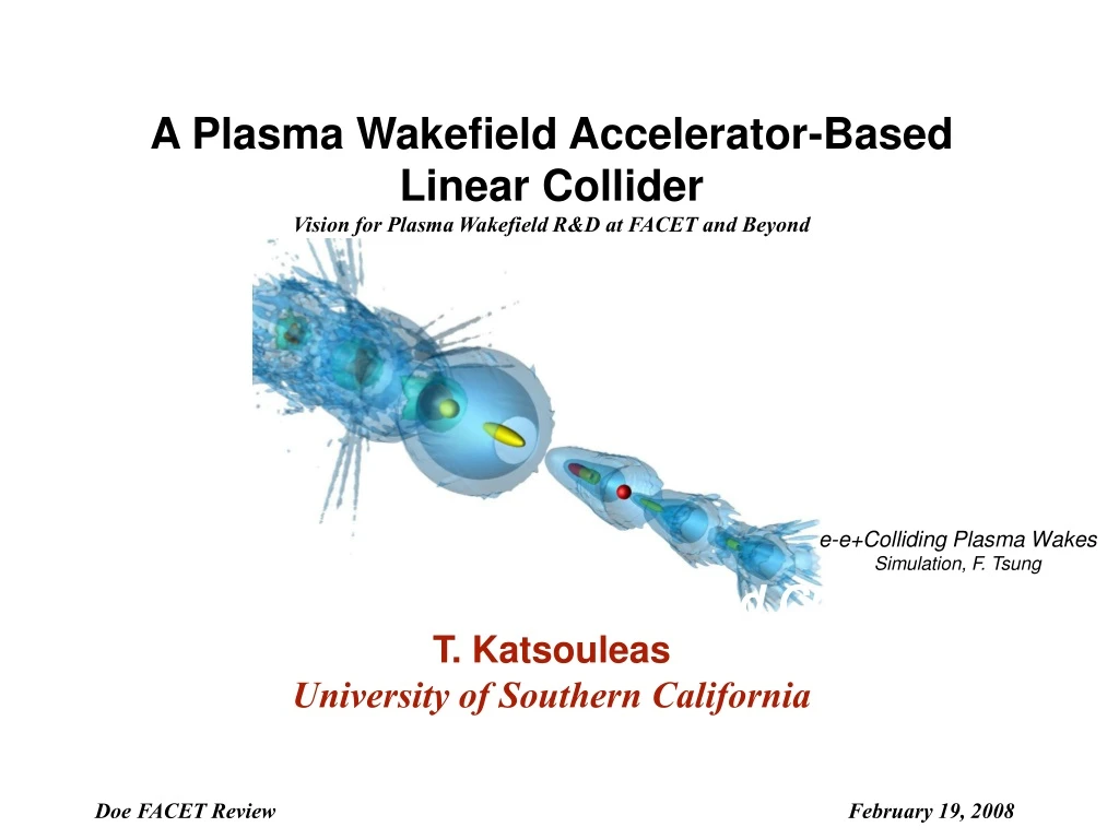
A Plasma Wakefield Accelerator-Based Linear Collider Vision for Plasma Wakefield R&D at FACET and Beyond. e-e+Colliding Plasma Wakes Simulation, F. Tsung. Beyond 10 GeV: Results, Plans and Critical Issues T. Katsouleas University of Southern California.

E N D
A Plasma Wakefield Accelerator-Based Linear Collider Vision for Plasma Wakefield R&D at FACET and Beyond e-e+Colliding Plasma Wakes Simulation, F. Tsung Beyond 10 GeV: Results, Plans and Critical Issues T. Katsouleas University of Southern California Doe FACET Review February 19, 2008
Outline • Brief History and Context • Introduction to plasma wakefield accelerators • Path to a high energy collider • Critical issues, milestones and timeframe • What can and cannot be addressed with FACET
ILC Current Energy Frontier E164X/E-167 LBL RAL LBL Osaka UCLA ANL Plasma Accelerators -- Brief History • 1979 Tajima & Dawson Paper • 1983 Tigner Panel rec’d investment in adv. acc. • 1985 Malibu, GV/m unloaded beat wave fields, world-wide effort begins • 1989 1st e- at UCLA • 1994 ‘Jet age’ begins (100 MeV in laser-driven gas jet at RAL) • 2004 ‘Dawn of Compact Accelerators’ (monoenergetic beams at LBL, LOA, RAL) • 2007 Energy Doubling at SLAC
Acceleration, Radiation Sources, Refraction, Medical Applications Research program has put Beam Physics at the Forefront of Science
Particle AcceleratorsRequirements for High Energy Physics • High Energy • High Luminosity (event rate) • L=fN2/4psxsy • High Beam Quality • Energy spread dg/g ~ .1 - 10% • Low emittance: en ~ gsyqy << 1 mm-mrad • Low Cost(one-tenth of $10B/TeV) • Gradients > 100 MeV/m • Efficiency > few %
E 1-D plasma density wave Simple Wave Amplitude Estimate Vph=c Gauss’ Law
Linear Plasma Wakefield Theory Large wake for a laser amplitude a beam density nb~ no For sz of order cpwp-1 ~ 30m (1017/no)1/2 and spot sizes=c/wp ~ 15m (1017/no)1/2 : • Q/ sz = 1nCoul/30m (I~10 kA) Requirements on I, t, s, g require a FACET-class facility Ultra-high gradient regime and long propagation issues not possible to access with a 50 MeV beam facility
- - - - - - - - - - - - - - - - - - - - - - - - - - - - - - - - - - - - - - - - - - - - - - - - - - - - - - - - - - - - - - - - - - - - - - - - - - + + + - - - - - - - - - drive beam + - - + + + + + - + + + + + - + + + + + + + - - - - + + + + + + + + + + + + + + + - - - - - - - - - - - - - - - - - - - - - - - + + + + + + + + + + + + + + + - - - - - - + + + + + + + + + + + + - - - - - - - + + + + + + + + + + + + + + + - - - - - - - - - - - - - - - - - - + + + + + + + + - - - - - - - - - Ez Nonlinear Wakefield Accelerators (Blowout Regime) Rosenzweig et al. 1990 • Plasma ion channel exerts restoring force => space charge oscillations • Linear focusing force on beams (F/r=2pne2/m) • Synchrotron radiation • Scattering
Limits to Energy Gain • Beam propagation • Head erosion (L=ps2/e) • Hosing • Transformer Ratio: E- load driver E+
U C L A PIC Simulations of beam loading Blowout regime flattens wake, reduces energy spread Beam load Ez Unloaded wake • Loaded wake • Nload~30% Nmax • 1% energy spread
px x s Several betatron periods (effective area increased) 1/4 betatron period (tails from nonlinear Fp ) Emittance Preservation • Emittance en = phase space area: Plasma focusing causes beam to rotate in phase space • Matching: Plasma focusing (~2pnoe2s) = Thermal pressure (grad p~e2/s3) • No spot size oscillations (phase space rotations) • No emittance growth Fp Fth
e- e+ Positron Acceleration -- two possibilitiesblowout or suck-in wakes e+ load • • Non-uniform focusing force (r,z) • Smaller accelerating force • Much smaller acceptance phase for acceleration and focusing Ref. S. Lee et al., Phys. Rev. E (2000); M. Zhou, PhD Thesis (2008)
Accelerator Comparison On ultra-fast timescales, relativistic plasmas can be robust, stable and disposable accelerating structures • No aperture, BBU TESLA structure l ~ 30cm 2a Plasma l ~ 100mm
Path to a TeV Colliderfrom present state-of-the-art* • Starting point: 42 --> 85 GeV in 1m • Few % of particles • Beam load • 25-50 GeV in ~ 1m • 2nd bunch with 33% of particles • Small energy spread • Replicate for positrons • Marry to high efficiency driver • Stage 20 times * I. Blumenfeld et al., Nature 445, 741 (2007)
CLIC-like PWFA LC Schematic ~120 MW AC power per side 12 usec trains of e- bunches accelerated to ~25 GeV Bunch population ~3 x 10¹⁰, 2 nsec spacing 100 trains / second ~2 km Drive Beam Accelerator ~60 MWdrive beam power per side ~20 MW main beam power per side PWFA Cells: DR 25 GeV in ~ 1 m, 20 per side ~100 m spacing DR Beam Delivery System, IR, and Main Beam Extraction / Dump Main Beam e- Source: ~ 4 km 500 nsec trains of e- bunches Bunch population ~1 x 10¹⁰, 2 nsec spacing 100 trains / second Main Beam e+ Source: 1TeV CM 500 nsec trains of e- bunches Bunch population ~1 x 10¹⁰, 2 nsec spacing 100 trains / second
mini-train 20 mini-train 1 500ns: 250bunches 2ns spacing 100ns kicker gap 12ms train • Drive Beam Source • DC or RF gun • Train format: • With 3 x 10¹⁰ /bunch @ 100Hz: • ~2.3 mA average current, ~2 A beam current, similar to beam successfully accelerated in CTF3 • Compress bunches to ~30 m RMS length • SPPS achieved much smaller RMS lengths • Accelerate to 25 GeV • Fully-loaded NC RF structures, similar to CLIC / CTF 3 • Inject into “Drive Beam Superhighway” with pulsed extraction for each PWFA cell • Both e+ and e- main beams use e- drive beam See slide notes for additional background
Drive Beam Superhighway • Based on CLIC drive beam scheme • Drive beam propagates opposite direction wrt main beam • Drive mini-train spacing = 2 * PWFA cell spacing i.e, ~600 nsec
Drive Beam Distribution • Format options • Mini-trains < 600 nsec • NC RF for drive beam • Duty cycle very low • Individual bunches > 12 μsec • SC RF for drive beam • Duty cycle ~100 %
Main Beam Source and Plasma Sections • Electron side: • DC gun + DR • Compress to 10m (achieved in SPPS) • 20, +25GeV plasma sections, each 1E17 density, <1.2 meters long • Gaussian beams assumed -shaped beam profiles => larger transformer ratio, higher efficiency • Final main beam energy spread <5% • Positron side: • conventional target + DR • Positron acceleration in electron beam driven wakes (regular plasma or hollow channel) • Will have tighter tolerances than electron side
Matching / Combining / Separating Main and Drive Beams • Must preserve bunch lengths • Preserve emittance of main beam • ~100 μm spacing of main and drive bunches • Time too short for a kicker – need magnetostatic combiner / separator • Need main – drive bunch timing at μm level • Different challenges at different energies • High main beam energy: emittance growth from SR • Low main beam energy: separation tricky because of ~equal beam energies • Need ~100 m between PWFA cells “First attempt” optics of 500 GeV / beam separator. First bend and first quad separate drive and main beam in x (they have different energies); combiner is same idea in reverse. This optics needs some tuning and ~2 sextupoles. System is isochronous to the level of ~1 μm R56. Assuming that another ~50 m needed for combiner, each PWFA cell needs ~100 m of optics around it.
TeV Beam Parameter Summary *If DR emittance is preserved
Other Paths to a Plasma-based Collider • Hi R options --> 100 GeV to TeV c.m. in single stage • Ramped drive bunches or bunch trains • Plasma question: hose stability • RF Driver questions: pulse shaping techniques, drive charge is 5x larger • SRF Driven Stages • 5 stage example of Yakimenko and Ischebeck • Plasma question: extrapolate to 2m long 100 GeV • SRF questions: 3x5 +1 times the power/m and loading of ILC, wakes and BBU • Laser drivers • Extrapolate 1 GeV experiments to 25 GeV • Scale up laser power x25, pulse length x5, density x0.04, plasma length x125 • 20 Stages • Plasma questions: channel guiding over 1m; injected e-; e+ behind bubble • Laser questions: Avg. laser power (20MW/h) needs to increase by 102-104
Red=FACET only Blue=FACET Green=Facet partial Critical Issues
Summary • Recent success is very promising • No known show stoppers to extending plasma accelerators to the energy frontier • Many questions remain to be addressed for realizing a collider • FACET-class facility is needed to address them • Lower energy beam facilities cannot access critical issues in the regime of interest • FACET can address most issues of one stage of a 5-20 stage e-e+ TeV collider
Future upgrade or alternative paths • PWFA can be an upgrade path of e-e- or gg options • The following flow corresponds to the afterburner path
Beam delivery • NLC style FF with local chromatic correction can be a starting point • ~TeV CM required just ~300m • Energy acceptance (full) was about 2% –within a factor of two from what is needed for PWFA-LC (further tweaking, L* optimization, etc) • Beam delivery length likely be dominated by collimation system (could be +1.0-1.5km/side) – methods like crystal collimation and nonlinear collimations to be looked at again An early (2000) design of NLC FF L* =2m by*=0.1mm
1 TeV Plasma Wakefield Accelerator PWFA Modules P ~10 µs+ ~1 ns Trailing Beam Trailing Beam 5, 100 GeV drive pulses, SC linac Ref.:V. Yakimenko and R. Ischebeck, AIP conference proceedings 877, p. 158 (2006).